Jtag tap controller state machine description, Jtag tap c, Ontroller – Rainbow Electronics DS3170 User Manual
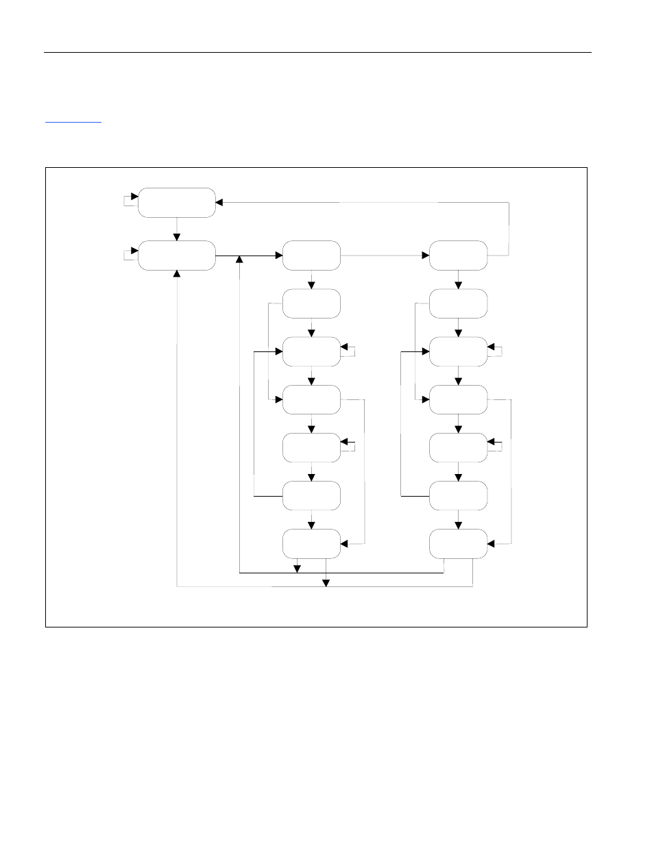
Page 203: Tate, Achine, Escription, Figure 12-2. jtag tap controller state machine, 2 jtag tap controller state machine description
DS3170 DS3/E3 Single-Chip Transceiver
203 of 233
12.2 JTAG TAP Controller State Machine Description
This section covers the details on the operation of the Test Access Port (TAP) Controller State Machine. See
for details on each of the states described below. The TAP controller is a finite state machine that
responds to the logic level at JTMS on the rising edge of JTCLK.
Figure 12-2. JTAG TAP Controller State Machine
Test-Logic-Reset
Run-Test/Idle
Select
DR-Scan
1
0
Capture-DR
1
0
Shift-DR
0
1
Exit1- DR
1
0
Pause-DR
1
Exit2-DR
1
Update-DR
0
0
1
Select
IR-Scan
1
0
Capture-IR
0
Shift-IR
0
1
Exit1-IR
1
0
Pause-IR
1
Exit2-IR
1
Update-IR
0
0
1
0
0
1
0
1
0
1
Test-Logic-Reset. When
JTRST is changed from low to high, the TAP controller starts in the Test-Logic-Reset
state, and the Instruction Register is loaded with the IDCODE instruction. All system logic and I/O pads on the
device operate normally. This state can also be reached from any other state by holding JTMS high and clocking
JTCLK five times.
Run-Test-Idle. Run-Test-Idle is used between scan operations or during specific tests. The Instruction Register
and Test Register remain idle.
Select-DR-Scan. All test registers retain their previous state. With JTMS low, a rising edge of JTCLK moves the
controller into the Capture-DR state and initiates a scan sequence. JTMS high moves the controller to the Select-
IR-Scan state.