Optional preamp, Clock and data recovery (cdr), Loss-of-signal (los) detector – Rainbow Electronics DS3170 User Manual
Page 115: Table 9-34. recommended transformers
DS3170 DS3/E3 Single-Chip Transceiver
115 of 233
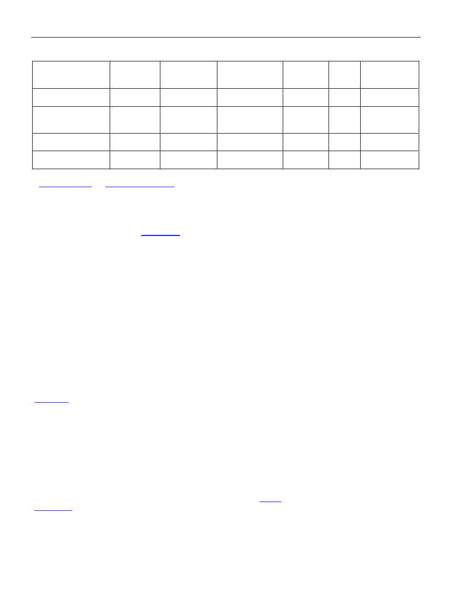
Table 9-34. Recommended Transformers
MANUFACTURER PART
TEMP
RANGE
PIN-PACKAGE/
SCHEMATIC
OCL
PRIMARY
(
mH) (min)
L
L
(
mH)
(max)
BANDWIDTH
75
W (MHz)
Pulse Engineering
PE-65968
0°C to +70°C
6 SMT
LS-1/C
19 0.06
0.250
to
500
Pulse Engineering
PE-65969
0°C to +70°C
6 Thru-Hole
LC-1/C
19 0.06
0.250
to
500
Halo Electronics
TG07-
0206NS
0°C to +70°C
6 SMT
SMD/B
19 0.06
0.250
to
500
Halo Electronics
TD07-
0206NE
0°C to +70°C
6 DIP
DIP/B
19 0.06
0.250
to
500
Note: Table subject to change. Industrial temperature range and multiport transformers are also available. Contact the manufacturers for details
at
9.12.5.2 Optional Preamp
The receiver can be used in monitoring applications, which typically have series resistors with a resistive loss of
approximately 20dB. When the
.RMON bit is high, the receiver compensates for this resistive loss by
applying flat gain to the incoming signal before sending the signal to the AGC/equalizer block.
9.12.5.3 Automatic Gain Control (AGC) and Adaptive Equalizer.
The AGC circuitry applies flat (frequency independent) gain to the incoming signal to compensate for flat losses in
the transmission channel and variations in transmission power. Since the incoming signal also experiences
frequency-dependent losses as it passes through the coaxial cable, the adaptive equalizer circuitry applies
frequency-dependent gain to offset line losses and restore the signal. The AGC/equalizer circuitry automatically
adapts to coaxial cable losses from 0 to 15dB, which translates into 0 to 380 meters (DS3) or 0 to 440 meters (E3)
of coaxial cable (AT&T 734A or equivalent). The AGC and the equalizer work simultaneously but independently to
supply a signal of nominal amplitude and pulse shape to the clock and data recovery block. The AGC/equalizer
block automatically handles direct (0 meters) monitoring of the transmitter output signal.
9.12.5.4 Clock and Data Recovery (CDR)
The CDR block takes the amplified, equalized signal from the AGC/equalizer block and produces a separate clock,
positive data, and negative data signals. The CDR requires a master clock. The master clock is derived from
REFCLK.
The receive clock is locked using a clock recovery PLL. The status of the PLL lock is indicated in the RLOL
(
) status bit. The receive loss-of-lock status bit (RLOL) is set when the difference between the recovered
clock frequency and the master clock frequency is greater than 7900ppm and cleared when the difference is less
than 7700ppm. A change of state of the PORT.SR.RLOL status bit can cause an interrupt on the
INT pin if enabled
to do so by the PORT.SRIE.RLOLIE interrupt-enable bit. Note that if the master clock is not present, or the master
clock is high and TCLK is not present, RLOL is not set.
9.12.5.5 Loss-of-Signal (LOS) Detector
The receiver contains analog and digital LOS detectors. The analog LOS detector resides in the AGC/equalizer
block. If the incoming signal level is less than a signal level approximately 24dB below nominal, analog LOS
(ALOS) is declared. The ALOS signal cannot be directly examined, but when ALOS occurs the AGC/equalizer
mutes the recovered data, forcing all zeros out of the data recovery circuitry and causing digital LOS (DLOS).
DLOS is determined by the Line Decoder block (see Section
) and indicated by the LOS status bit
(
LOS).
ALOS clears when the incoming signal level is greater than or equal to a signal level approximately 18dB below
nominal.
For E3 LOS Assertion: