Features, B3zs/hdb3 encoder, Transmit line interface – Rainbow Electronics DS3170 User Manual
Page 105: Figure 9-24. line encoder/decoder block diagram, Figure 9-24, 2 features, 3 b3zs/hdb3 encoder, 4 transmit line interface
DS3170 DS3/E3 Single-Chip Transceiver
105 of 233
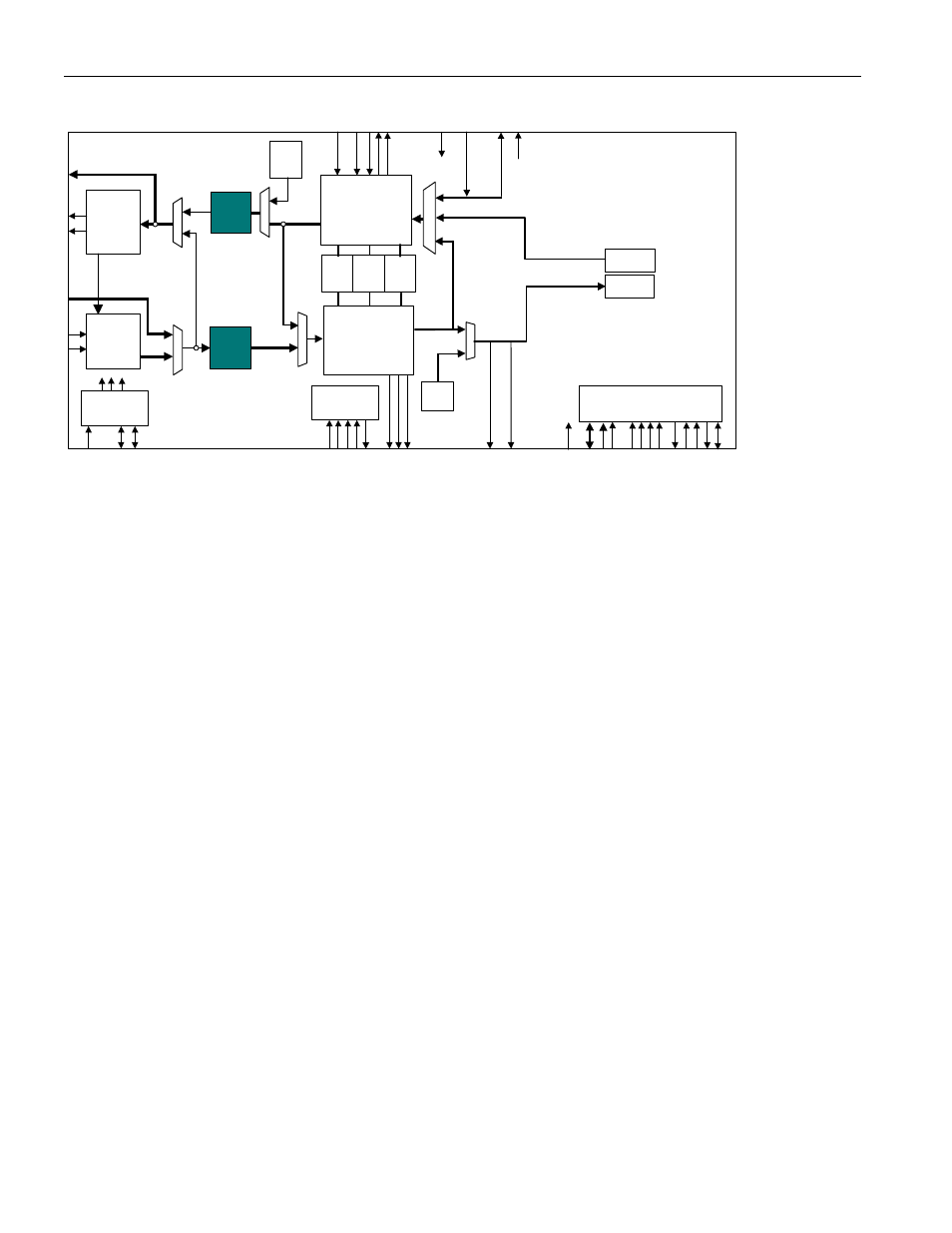
Figure 9-24. Line Encoder/Decoder Block Diagram
DS3/E3
Transmit
LIU
IEEE P1149.1
JTAG Test
Access Port
Microprocessor
Interface
HDLC
FEAC
LLB
DL
B
DS3 / E3
Transmit
Formatter
DS3 / E3
Receive
Framer
Trail
Trace
Buffer
DS3/E3
Receive
LIU
TAIS
TUA1
Clock Rate
Adapter
TX BERT
RX BERT
PL
B
AL
B
UA1
GEN
B3ZS/
HDB3
Encoder
B3ZS/
HDB3
Decoder
9.10.2 Features
· Performs bipolar to unipolar encoding and decoding – Converts a unipolar signal into an AMI bipolar signal
(POS data, and NEG data) and vice versa.
· Programmable zero suppression – B3ZS or HDB3 zero suppression encoding and decoding can be
performed, or the bipolar data stream can be left as an AMI encoded data stream.
· Programmable receive zero suppression code format – The signature of B3ZS or HDB3 is selectable.
· Generates and detects alarms and errors – In the receive direction, detects LOS alarm condition BPV
errors, and EXZ errors. In the transmit direction, errors can be inserted into the outgoing data stream.
9.10.3 B3ZS/HDB3 Encoder
B3ZS/HDB3 Encoder performs unipolar to bipolar conversion and zero suppression encoding.
Unipolar to bipolar conversion converts the unipolar data stream into an AMI bipolar data stream (POS and NEG).
In an AMI bipolar data stream a zero is represented by a zero on both the POS and NEG signals, and a one is
represented by a one on a bipolar signal (POS or NEG), and a zero on the other bipolar signal (NEG or POS).
Successive ones are represented by ones that are alternately output on the POS and NEG signals. i.e., if a one is
represented by a one on POS and a zero on NEG, the next one will be represented by a one on NEG and a zero
on POS.
Zero suppression encoding converts an AMI bipolar data stream into a B3ZS or HDB3 encoded bipolar data
stream. A B3ZS encoded bipolar signal is generated by inserting a B3ZS signature into the bipolar data stream if
both the POS and NEG signals are zero for three consecutive clock periods. An HDB3 encoded bipolar signal is
generated by inserting an HDB3 signature into the bipolar data stream if both the POS and NEG signals are zero
for four consecutive clock periods. Zero suppression encoding can be disabled which will result in AMI-coded data.
Error insertion is also performed. Error insertion inserts bipolar violation (BPV) or excessive zero (EXZ) errors onto
the bipolar signal. A BPV error will be inserted when three consecutive ones occur. An EXZ error will be inserted
when three (or four) consecutive zeros on the bipolar signal occur by inhibiting the insertion of a B3ZS (HDB3)
signature. There will be at least one intervening pulse between consecutive BPV or EXZ errors. A single BPV or
EXZ error inserted will be detected as a single BPV/EXZ error at the far-end, and will not cause any other type of
error to be detected. For example, if a BPV error is inserted, the far-end should not also detect a data error.
9.10.4 Transmit Line Interface
The Transmit Line Interface accepts a bipolar data stream from the B3ZS/HDB3 Encoder, performs error insertion,
and transmits the bipolar data stream.
Error insertion inserts BPV or EXZ errors into the bipolar signal. When a BPV error is to be inserted, the Transmit
Line Interface waits for the next occurrence of three consecutive ones. The first bipolar one is generated according
to the normal AMI rules. The second bipolar one is generated by transmitting the same values on TPOS and TNEG