Transmit g.832 e3 register map, Register bit descriptions, Table 11-26. transmit g.832 e3 framer register map – Rainbow Electronics DS3170 User Manual
Page 191: E3g832.tcr
DS3170 DS3/E3 Single-Chip Transceiver
191 of 233
11.9.5 Transmit G.832 E3 Register Map
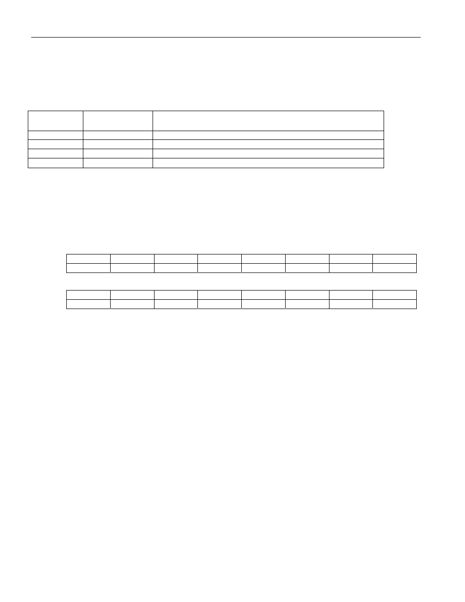
The transmit G.832 E3 utilizes four registers.
Table 11-26. Transmit G.832 E3 Framer Register Map
Address
Register
Register Description
118h
E3G832.TCR
E3 G.832 Transmit Control Register
11Ah
E3G832.TEIR
E3 G.832 Transmit Error Insertion Register
11Ch
E3G832.TMABR
E3 G.832 Transmit MA Byte Register
11Eh
E3G832.TNGBR
E3 G.832 Transmit NR and GC Byte Register
11.9.5.1 Register Bit Descriptions
Register Name:
E3G832.TCR
Register Description:
E3 G.832 Transmit Control Register
Register Address:
118h
Bit
# 15 14 13 12 11 10 9 8
Name
Reserved --
-- Reserved Reserved TGCC
TNRC1 TNRC0
Default
0 0 0 0 0 0 0 0
Bit
# 7 6 5 4 3 2 1 0
Name -- -- TFEBE
AFEBED
TRDI
ARDID
TFGD
TAIS
Default
0 0 0 0 0 0 0 0
Bit 10: Transmit GC Byte Control (TGCC) – When 0, the GC byte is inserted from the transmit HDLC controller .
When 1, the GC byte is inserted from the GC byte register.
Note: If bit TGCC is 0 and TNRC[1:0] is 01, both the GC byte and NR byte will carry the same transmit HDLC
controller (eight bits per frame period), however, the GC byte and NR byte in the same frame may or may not be
equal.
Bits 9 to 8: Transmit NR Byte Control (TNRC[1:0]) – These two bits control the source of the NR byte.
00 = all ones.
01 = transmit from the HDLC controller.
10 = transmit from the FEAC controller.
11 = NR byte register.
Note: If TNRC[1:0] is 01 and TGCC is 0, both the NR byte and GC byte will carry the same transmit HDLC
controller (eight bits per frame period), however, the NR byte and GC byte in the same frame may or may not be
equal.
Bit 5: Transmit REI Error (TFEBE) – When automatic REI generation is defeated (AFEBED = 1), this bit is
inserted into the second bit of the MA byte.
Bit 4: Automatic REI Defeat (AFEBED) – When 0, the REI is automatically generated based upon the transmit
remote error indication (TREI) signal. When 1, the REI is inserted from the register bit TFEBE.
Bit 3: Transmit RDI Alarm (TRDI) – When automatic RDI generation is defeated (ARDID = 1), this bit is inserted
into the first bit of the MA byte.
Bit 2: Automatic RDI Defeat (ARDID) – When 0, the RDI is automatically generated based upon the received E3
alarms. When 1, the RDI is inserted from the register bit TRDI.
Bit 1: Transmit Frame Generation Disabled (TFGD) –
0 = Transmit Frame Generation is enabled