E3g751.rsrie2, E3g751.rfecr – Rainbow Electronics DS3170 User Manual
Page 190
DS3170 DS3/E3 Single-Chip Transceiver
190 of 233
Bit 2: Alarm Indication Signal Interrupt Enable (AISIE) – This bit enables an interrupt if the AISL bit is set and
the bit in
.PSRIE[4:1] that corresponds to this port is set.
0 = interrupt disabled
1 = interrupt enabled
Bit 1: Out Of Frame Interrupt Enable (OOFIE) – This bit enables an interrupt if the OOFL bit is set and the bit in
.PSRIE[4:1] that corresponds to this port is set.
0 = interrupt disabled
1 = interrupt enabled
Bit 0: Loss Of Signal Interrupt Enable (LOSIE) – This bit enables an interrupt if the LOSL bit is set and the bit in
.PSRIE[4:1] that corresponds to this port is set.
0 = interrupt disabled
1 = interrupt enabled
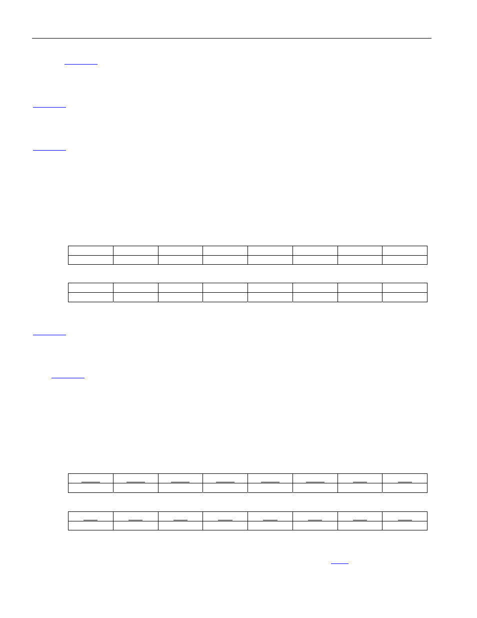
Register Name:
E3G751.RSRIE2
Register Description:
E3 G.751 Receive Status Register Interrupt Enable #2
Register Address:
12Eh
Bit
# 15 14 13 12 11 10 9 8
Name
-- -- -- --
Reserved
Reserved
Reserved
FEIE
Default
0 0 0 0 0 0 0 0
Bit
# 7 6 5 4 3 2 1 0
Name
-- -- -- --
Reserved
Reserved
Reserved
FECIE
Default
0 0 0 0 0 0 0 0
Bit 8: Framing Error Interrupt Enable (FEIE) – This bit enables an interrupt if the FEL bit is set and the bit in
.PSRIE[4:1] that corresponds to this port is set.
0 = interrupt disabled
1 = interrupt enabled
Bit 0: Framing Error Count Interrupt Enable (FECIE) – This bit enables an interrupt if the FECL bit is set and the
bit in
.PSRIE[4:1] that corresponds to this port is set.
0 = interrupt disabled
1 = interrupt enabled
Register Name:
E3G751.RFECR
Register Description:
E3 G.751 Receive Framing Error Count Register
Register Address:
134h
Bit
# 15 14 13 12 11 10 9 8
Name FE15 FE14 FE13 FE12 FE11 FE10 FE9 FE8
Default
0 0 0 0 0 0 0 0
Bit #
7 6 5 4 3 2 1 0
Name FE7 FE6 FE5 FE4 FE3 FE2 FE1 FE0
Default
0 0 0 0 0 0 0 0
Bits 15 to 0: Framing Error Count (FE[15:0]) – These sixteen bits indicate the number of framing error events on
the incoming E3 data stream. This register is updated via the PMU signal (see section