Trail trace, Trail trace transmit side, Register bit descriptions – Rainbow Electronics DS3170 User Manual
Page 168: Rail, Race, Tt.tcr
DS3170 DS3/E3 Single-Chip Transceiver
168 of 233
11.8 Trail Trace
11.8.1 Trail Trace Transmit Side
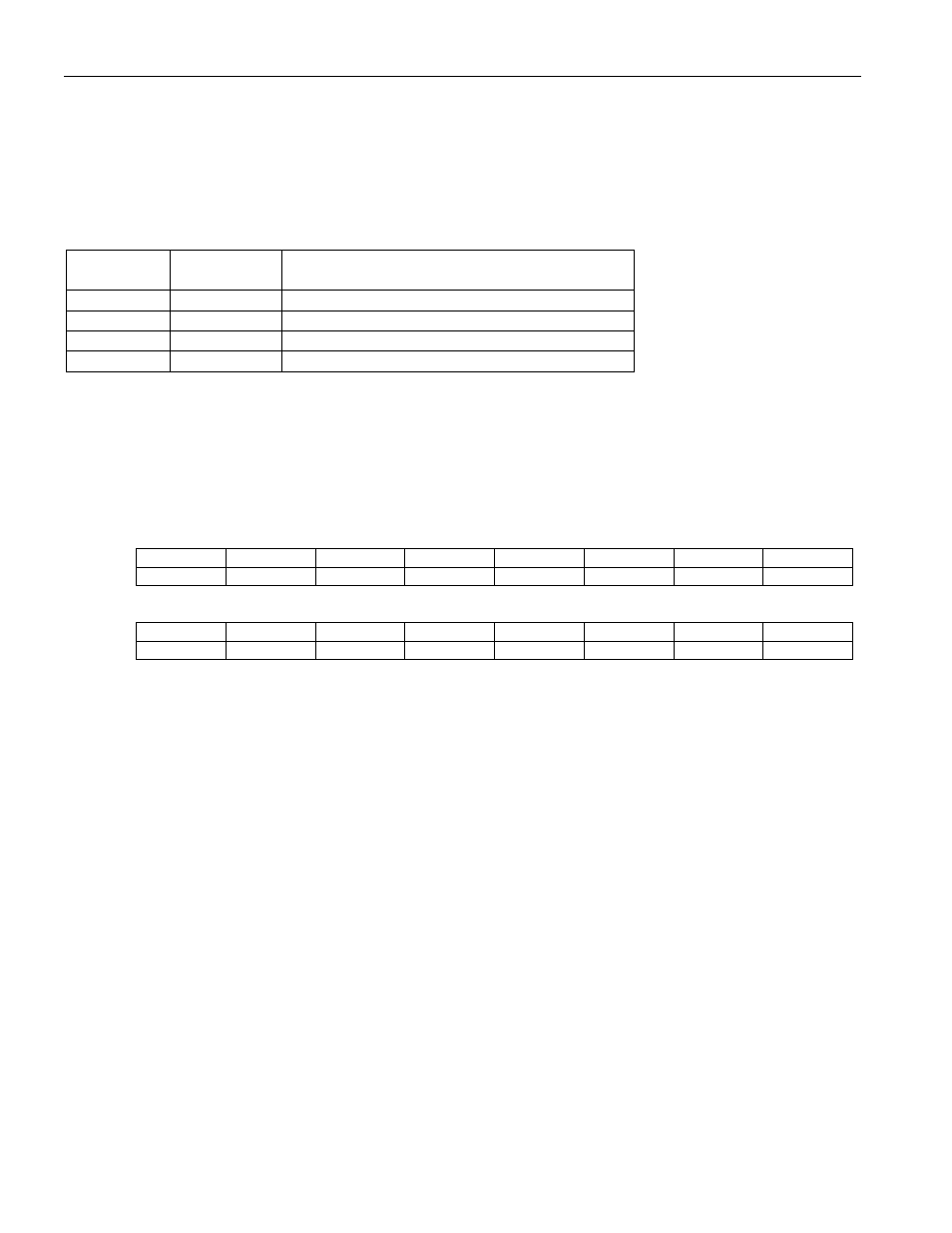
The transmit side utilizes three registers.
Table 11-20. Transmit Side Trail Trace Register Map
Address
Register
Register Description
0E8h TT.TCR
Trail Trace Transmit Control Register
0EAh TT.TTIAR
Trail Trace Transmit Identifier Address Register
0ECh TT.TIR
Trail Trace Transmit Identifier Register
0EEh --
Unused
11.8.1.1 Register Bit Descriptions
Register Name:
TT.TCR
Register Description:
Trail Trace Transmit Control Register
Register Address:
0E8h
Bit
# 15 14 13 12 11 10 9 8
Name
-- -- -- -- -- -- -- --
Default
0 0 0 0 0 0 0 0
Bit
# 7 6 5 4 3 2 1 0
Name
-- -- --
Reserved
TMAD
TIDLE
TDIE
TBRE
Default
0 0 0 0 0 0 0 0
Bit 3: Transmit Multiframe Alignment Insertion Disable (TMAD) – When 0, multiframe alignment signal (MAS)
insertion is enabled, and the first bit transmitted of each trail trace byte is overwritten with an MAS bit. When 1,
MAS insertion is disabled, and the trail trace bytes from the Transmit Data Storage are output without being
modified.
Bit 2: Transmit Trail Trace Identifier Idle (TIDLE) – When 0, the programmed transmit trail trace identifier will be
transmitted. When 1, all zeros will be transmitted.
Bit 1: Transmit Data Inversion Enable (TDIE) – When 0, the outgoing data from trail trace processing is output
directly. When 1, the outgoing data from trail trace processing is inverted before being output.
Bit 0: Transmit Bit Reordering Enable (TBRE) – When 0, bit reordering is disabled (The first bit transmitted is the
MSB TT.TIR.TTD[7] of the byte). When 1, bit reordering is enabled (The first bit transmitted is the LSB
TT.TIR.TTD[0] of the byte).