Ds3/e3 framer, Transmit ds3, Register bit descriptions – Rainbow Electronics DS3170 User Manual
Page 174: Ds3/e3, Framer, Table 11-22. transmit ds3 framer register map, T3.tcr
DS3170 DS3/E3 Single-Chip Transceiver
174 of 233
11.9 DS3/E3 framer
11.9.1 Transmit DS3
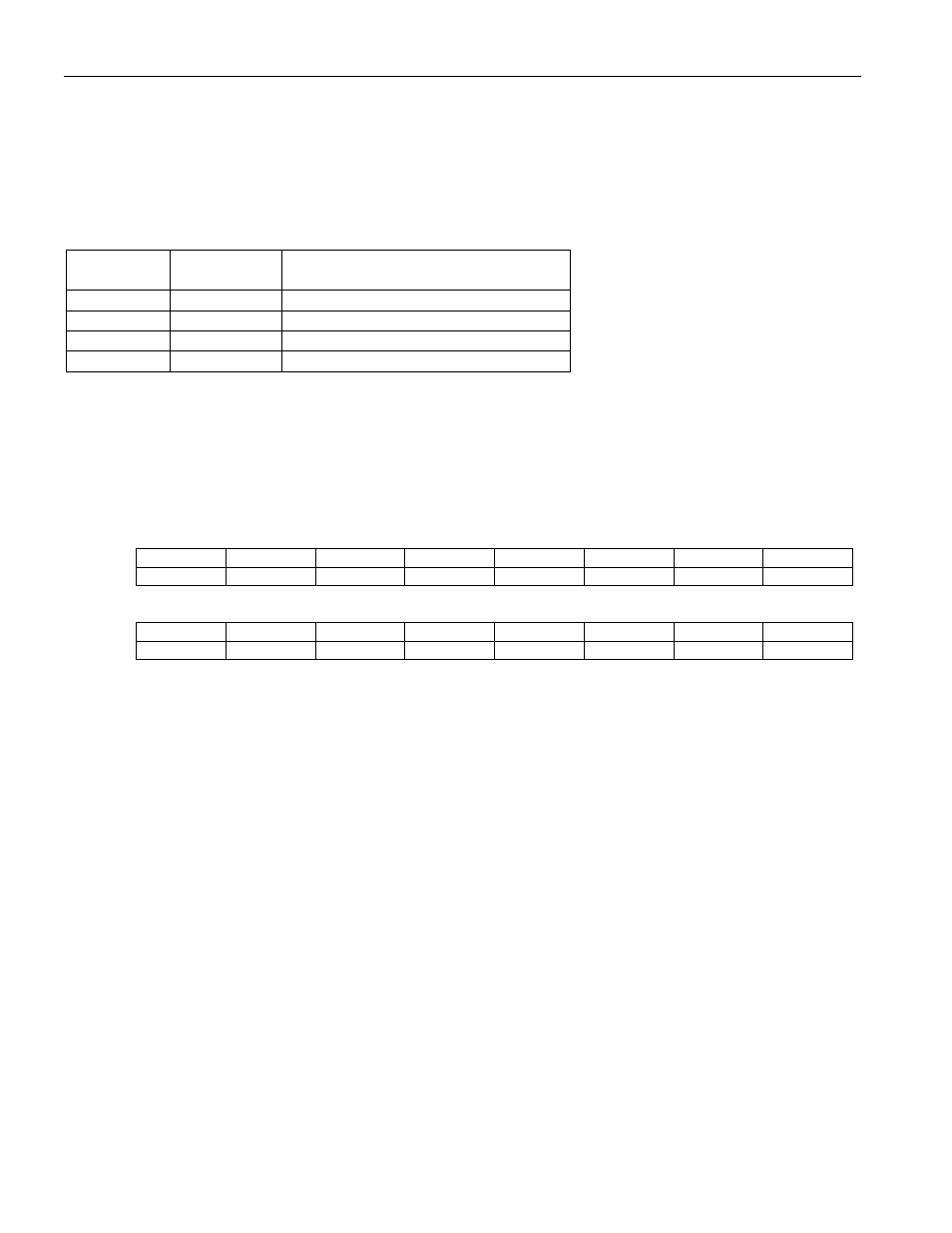
The transmit DS3 utilizes two registers.
Table 11-22. Transmit DS3 Framer Register Map
Address
Register
Register Description
118h T3.TCR
T3 Transmit Control Register
11Ah T3.TEIR
T3 Transmit Error Insertion Register
11Ch --
Reserved
11Eh --
Reserved
11.9.1.1 Register Bit Descriptions
Register Name:
T3.TCR
Register Description:
T3 Transmit Control Register
Register Address:
118h
Bit
# 15 14 13 12 11 10 9 8
Name
-- -- --
PBGE
TIDLE
CBGD
-- --
Default
0 0 0 0 0 0 0 0
Bit
# 7 6 5 4 3 2 1 0
Name -- -- TFEBE
AFEBED
TRDI
ARDID
TFGD
TAIS
Default
0 0 0 0 0 0 0 0
Bit 12: P-bit Generation Enable (PBGE) – When 0, if transmit frame generation is disabled, Transmit Frame
Processor P-bit generation is disabled. The P-bit overhead periods in the incoming T3 signal will be passed
through to error insertion. When 1, Transmit Frame Processor P-bit generation is enabled. The P-bit overhead
periods in the incoming T3 signal will be overwritten even if transmit frame generation is disabled.
Bit 11: Transmit DS3 Idle Signal (TIDLE) –
0 = Transmit DS3 Idle signal is not inserted
1 = Transmit DS3 Idle signal is inserted into the DS3 frame.
Bit 10: C-bit Generation Disable (CBGD) (M23 mode only) – When 0, Transmit Frame Processor C-bit
generation is enabled. The C-bit overhead periods in the incoming M23 DS3 signal will be overwritten with zeros.
When 1, Transmit Frame Processor C-bit generation is disabled. The C-bit overhead periods in the incoming M23
DS3 signal will be treated as payload, and passed through to overhead insertion. This bit is ignored in C-bit DS3
mode.
Bit 5: Transmit FEBE Error (TFEBE) – When automatic far-end block error generation is defeated (AFEBED = 1),
the inverse of this bit is inserted into the bits C
41
, C
42
, and C
43
. Note: a far-end block error value of zero (TFEBE=1)
indicates a far-end block error. This bit is ignored in M23 DS3 mode.
Bit 4: Automatic FEBE Defeat (AFEBED) – When 0, a far-end block error is automatically generated based upon
the receive C-bit parity errors or framing errors. When 1, a far-end block error is inserted from the register bit
TFEBE. This bit is ignored in M23 DS3 mode.
Bit 3: Transmit RDI Alarm (TRDI) – When automatic RDI generation is defeated (ARDID = 1), the inverse of this
bit is inserted into the X-bits (X
1
and X
2
). Note: an RDI value of zero (TRDI=1) indicates an alarm.
Bit 2: Automatic RDI Defeat (ARDID) – When 0, the RDI is automatically generated based received DS3 alarms.
When 1, the RDI is inserted from the register bit TRDI.