Figure 9-13. ds3 frame format, Figure 9-14. ds3 subframe framer state diagram, Sync load verify – Rainbow Electronics DS3170 User Manual
Page 81
DS3170 DS3/E3 Single-Chip Transceiver
81 of 233
Figure 9-13. DS3 Frame Format
680 Bits
7 Sub-
Frames
X
1
X
2
P
1
P
2
M
1
M
2
M
3
F
11
F
21
F
31
F
41
F
51
F
61
F
71
F
12
F
22
F
32
F
42
F
52
F
62
F
72
F
13
F
23
F
33
F
43
F
53
F
63
F
73
F
14
F
24
F
34
F
44
F
54
F
64
F
74
C
11
C
21
C
31
C
41
C
51
C
61
C
71
C
12
C
22
C
32
C
42
C
52
C
62
C
72
C
13
C
23
C
33
C
43
C
53
C
63
C
73
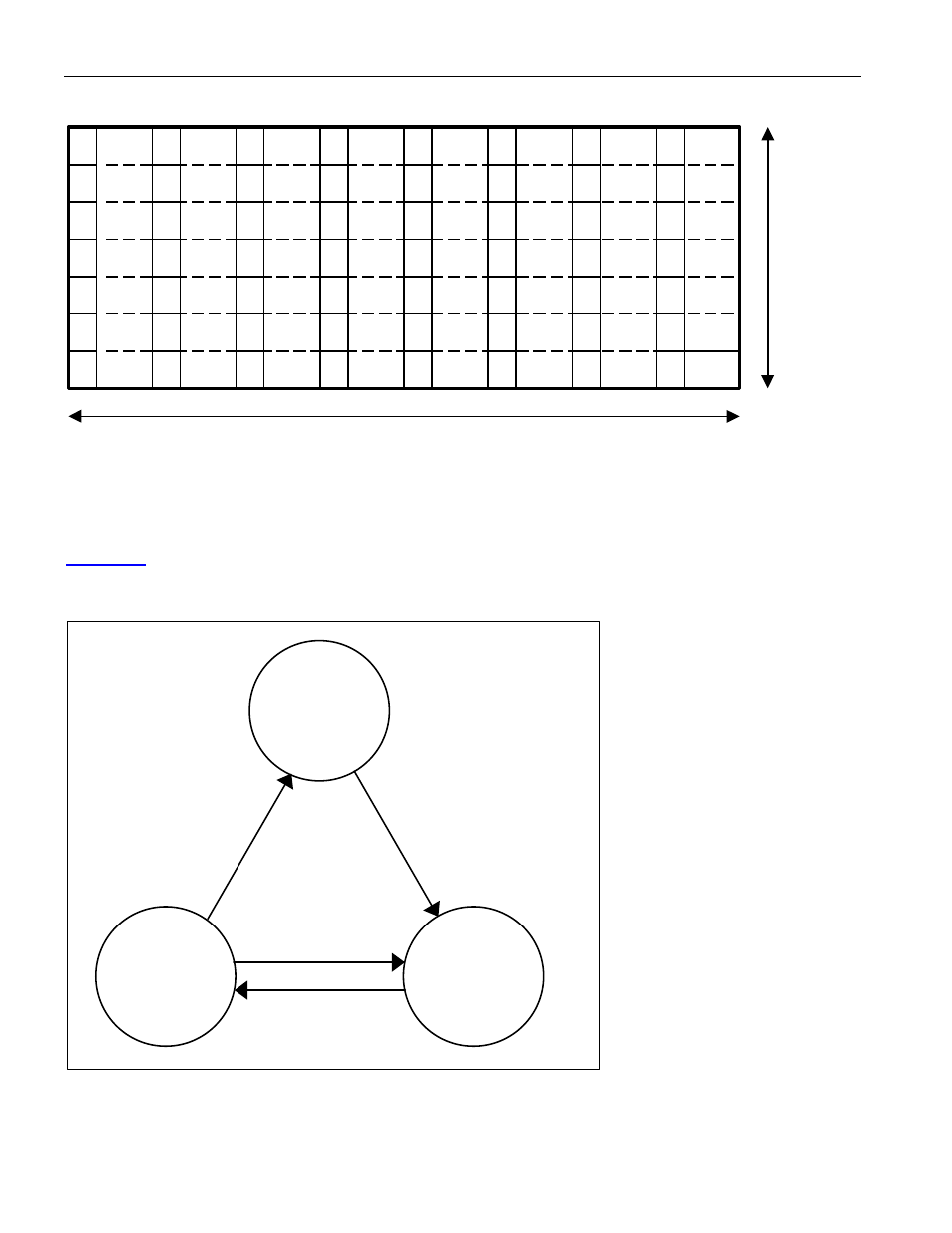
The subframe framer continually searches four adjacent bit positions for a subframe boundary. A subframe
alignment bit (F-bit) checker checks each bit position. All four bit positions must fail before any other bit positions
are checked for a subframe boundary. There are 170 possible bit positions that must be checked, and four
positions are checked simultaneously. Therefore up to 43 checks may be needed to identify the subframe
boundary. The subframe framer enables the multiframe frame once it has identified a subframe boundary. Refer to
for the subframe framer state diagram.
Figure 9-14. DS3 Subframe Framer State Diagram
Sync
Load
Verify
All 4 bit positions failed
2 F-bits loaded
3
bi
t p
os
iti
on
s
fa
ile
d
or
16
F
-b
its
v
er
ifi
ed
A
ll 4
bi
t p
os
itio
ns
fa
ile
d
The multiframe framer checks for a multiframe boundary. When the multiframe framer identifies a multiframe
boundary, it updates the data path frame counters if either an OOF or OOMF condition is present. The multiframe
framer waits until a subframe boundary has been identified. Then, each bit position is checked for the multiframe