Gl.isrie, Gl.isr – Rainbow Electronics DS3170 User Manual
Page 130
DS3170 DS3/E3 Single-Chip Transceiver
130 of 233
Bits 1 to 0: General Purpose IO 1 Select [1:0] (GPIO1S[1:0]). These bits determine the function of the GPIO1
pin.
00 = Input
01 = Port A status output selected by
:GPIOA[3:0] in port control registers
10 = Output logic 0
11 = Output logic 1
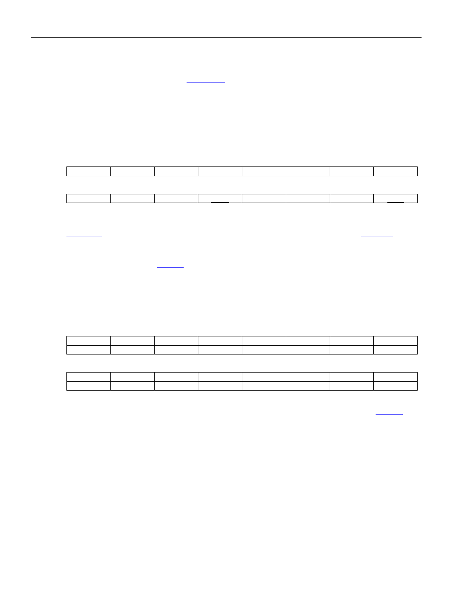
Register Name:
GL.ISR
Register Description:
Global Interrupt Status Register
Register Address:
010h
Bit
# 15 14 13 12 11 10 9 8
Name
-- -- -- -- -- -- -- --
Bit
# 7 6 5 4 3 2 1 0
Name
-- -- --
PISR -- --
--
GSR
Bit 4: Port Interrupt Status Register (PISR) This bit is set when any of the bits in the port interrupt status
registers (
) are set. The
INT interrupt pin will be driven low when this bit is set and the
.PISRIE
interrupt enable bit is enabled.
Bit 0: Global Status Register Interrupt Status (GSR) This bit is set when any of the latched status register bits
in the global latched status register (
) are set and enabled for interrupt. The
INT interrupt pin will be driven
low when this bit is set and the GL.ISRIE.GSRIE interrupt enable bit is enabled.
Register Name:
GL.ISRIE
Register Description:
Global Interrupt Status Register Interrupt Enable
Register Address:
012h
Bit
# 15 14 13 12 11 10 9 8
Name
-- -- -- -- -- -- -- --
Default
0 0 0 0 0 0 0 0
Bit
# 7 6 5 4 3 2 1 0
Name
-- -- --
PISRIE
-- --
RESERVED
GSRIE
Default
0 0 0 0 0 0 0 0
Bit 4: Port Interrupt Status Register Interrupt Enable (PISRIE) When this is enabled and the
PISR
status bit is set, the
INT pin will be driven low.
0 = interrupt disabled
1 = interrupt enabled
Bit 0: Global Status Register Interrupt Status Interrupt Enable (GSRIE) When this interrupt enable bit is
enabled, and the GL.ISR.GSR status bit is set, the
INT pin will be driven low.
0 = interrupt disabled
1 = interrupt enabled