T3.rfecr, T3.rpecr – Rainbow Electronics DS3170 User Manual
Page 182
DS3170 DS3/E3 Single-Chip Transceiver
182 of 233
Bit 2: Far-End Block Error Count Interrupt Enable (FBECIE) – This bit enables an interrupt if the FBECL bit is
set and the bit in
.PSRIE[4:1] that corresponds to this port is set.
0 = interrupt disabled
1 = interrupt enabled
Bit 1: P-bit Parity Error Count Interrupt Enable (PECIE) – This bit enables an interrupt if the PECL bit is set and
the bit in
.PSRIE[4:1] that corresponds to this port is set.
0 = interrupt disabled
1 = interrupt enabled
Bit 0: Framing Error Count Interrupt Enable (FECIE) – This bit enables an interrupt if the FECL bit is set and the
bit in
.PSRIE[4:1] that corresponds to this port is set.
0 = interrupt disabled
1 = interrupt enabled
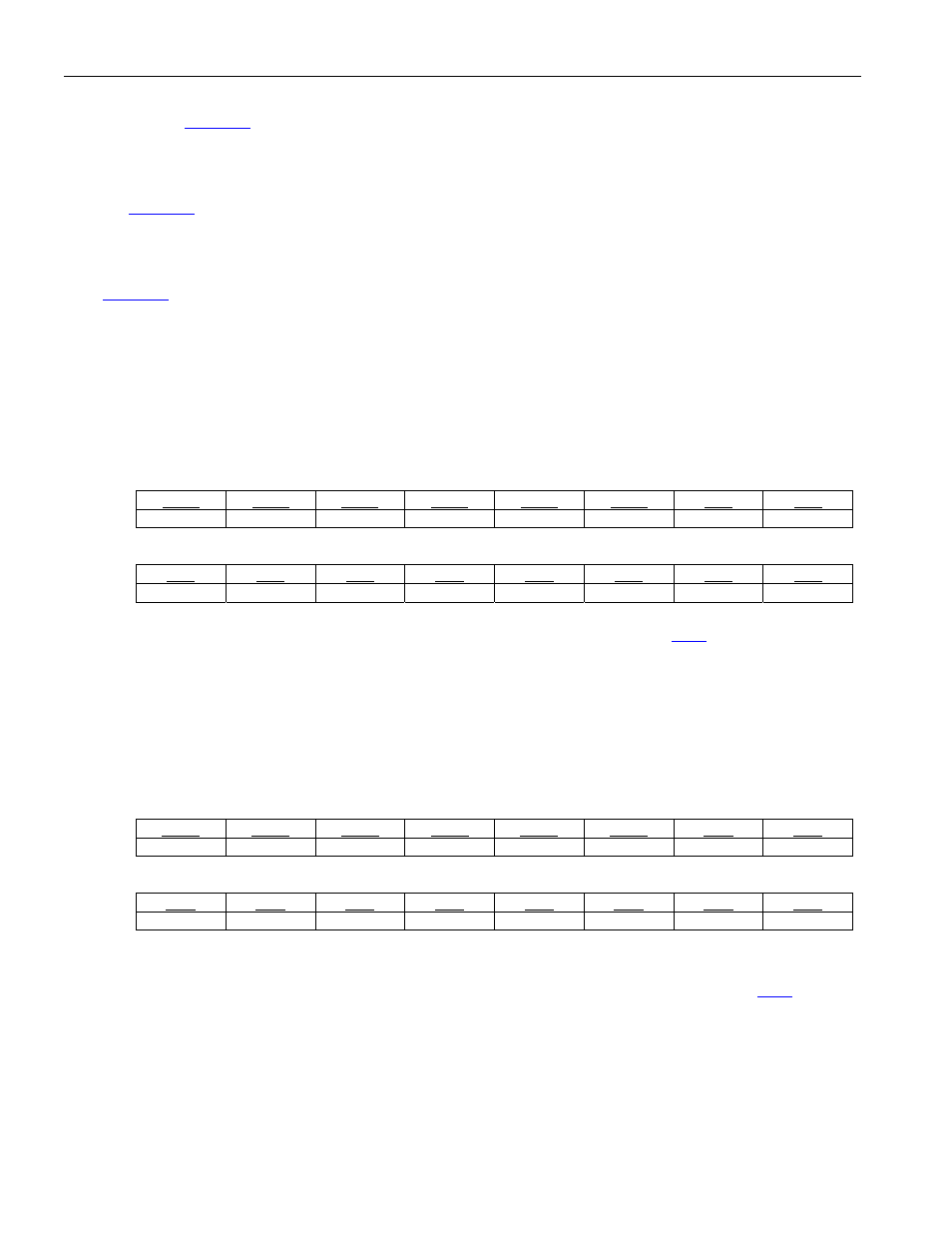
Register Name:
T3.RFECR
Register Description:
T3 Receive Framing Error Count Register
Register Address:
134h
Bit
# 15 14 13 12 11 10 9 8
Name FE15 FE14 FE13 FE12 FE11 FE10 FE9 FE8
Default
0 0 0 0 0 0 0 0
Bit
# 7 6 5 4 3 2 1 0
Name FE7 FE6 FE5 FE4 FE3 FE2 FE1 FE0
Default
0 0 0 0 0 0 0 0
Bits 15 to 0: Framing Error Count (FE[15:0]) – These sixteen bits indicate the number of framing error events on
the incoming DS3 data stream. This register is updated via the PMU signal (see section
Register Name:
T3.RPECR
Register Description:
T3 Receive P-bit Parity Error Count Register
Register Address:
136h
Bit
# 15 14 13 12 11 10 9 8
Name PE15 PE14 PE13 PE12 PE11 PE10 PE9 PE8
Default
0 0 0 0 0 0 0 0
Bit
# 7 6 5 4 3 2 1 0
Name PE7 PE6 PE5 PE4 PE3 PE2 PE1 PE0
Default
0 0 0 0 0 0 0 0
Bits 15 to 0: P-bit Parity Error Count (PE[15:0]) – These sixteen bits indicate the number of P-bit parity errors
detected on the incoming DS3 data stream. This register is updated via the PMU signal (see section