Gl.giocr – Rainbow Electronics DS3170 User Manual
Page 129
DS3170 DS3/E3 Single-Chip Transceiver
129 of 233
Register Name:
GL.GIOCR
Register Description:
Global General Purpose IO Control Register
Register Address:
00Ah
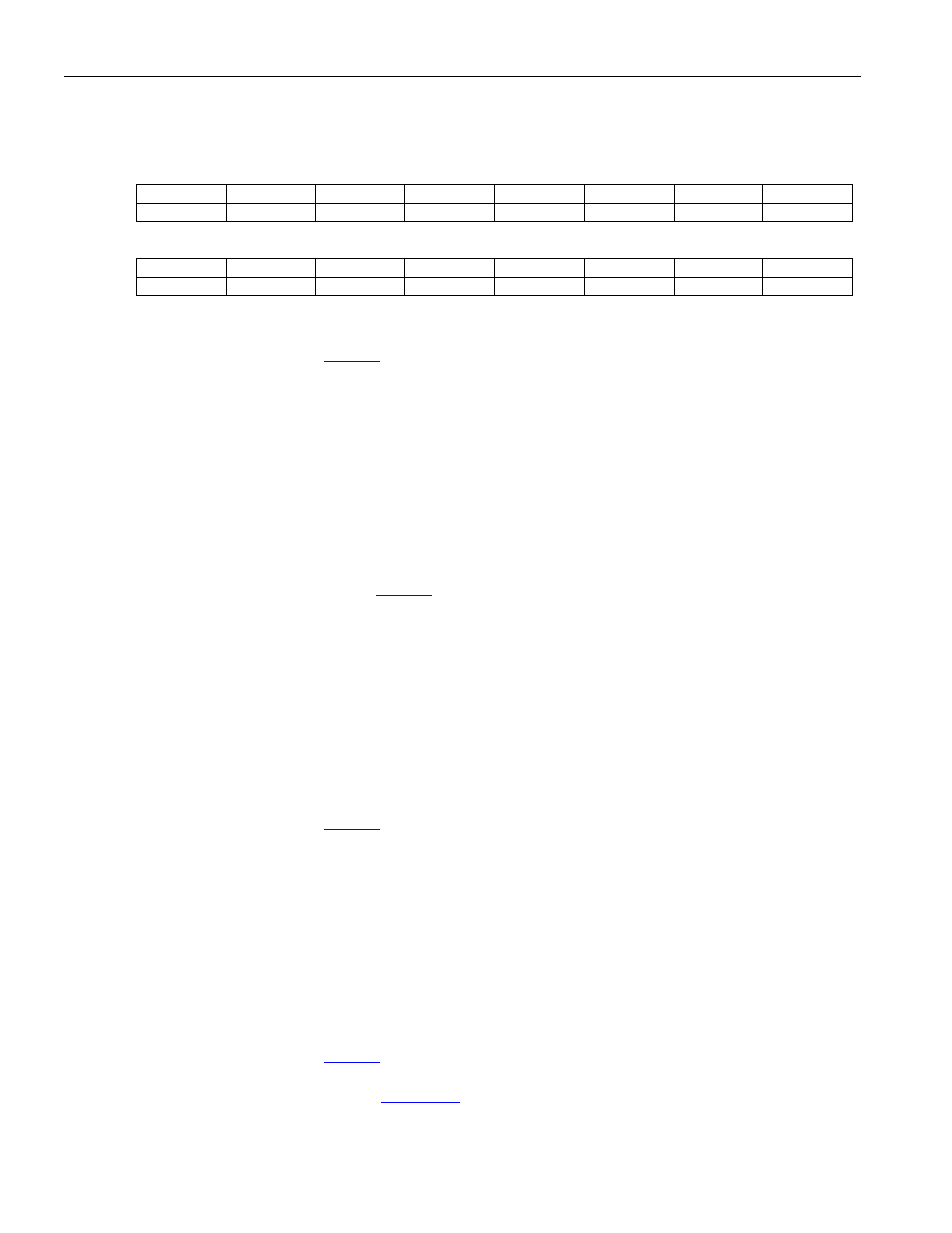
Bit
# 15 14 13 12 11 10 9 8
Name GPIO8S1 GPIO8S0 GPIO7S1 GPIO7S0 GPIO6S1 GPIO6S0 GPIO5S1 GPIO5S0
Default
0 0 0 0 0 0 0 0
Bit
# 7 6 5 4 3 2 1 0
Name GPIO4S1 GPIO4S0 GPIO3S1 GPIO3S0 GPIO2S1 GPIO2S0 GPIO1S1 GPIO1S0
Default
0 0 0 0 0 0 0 0
Bits 15 to 14: General Purpose IO 8 Select [1:0] (GPIO8S[1:0]). These bits determine the function of the GPIO8
pin. These selections are only valid if
.GPM[1:0] is not set to 01.
00 = Input
01 = Reserved
10 = Output logic 0
11 = Output logic 1
Bits 13 to 12: General Purpose IO 7 Select [1:0] (GPIO7S[1:0]). These bits determine the function of the GPIO7
pin.
00 = Input
01 = Reserved
10 = Output logic 0
11 = Output logic 1
Bits 11 to 10 : General Purpose IO 6 Select [1:0] (GPIO6S[1:0]). These bits determine the function of the
GPIO6 pin. These selections are only valid if
.MEIMS=0.
00 = Input
01 = Reserved
10 = Output logic 0
11 = Output logic 1
Bits 9 to 8: General Purpose IO 5 Select [1:0] (GPIO5S[1:0]). These bits determine the function of the GPIO5
pin.
00 = Input
01 = Reserved
10 = Output logic 0
11 = Output logic 1
Bits 7 to 6: General Purpose IO 4 Select [1:0] (GPIO4S[1:0]). These bits determine the function of the GPIO4
pin. These selections are only valid if
.G8KRIS=0.
00 = Input
01 = Reserved
10 = Output logic 0
11 = Output logic 1
Bits 5 to 4: General Purpose IO 3 Select [1:0] (GPIO3S[1:0]). These bits determine the function of the GPIO3
pin.
00 = Input
01 = Reserved
10 = Output logic 0
11 = Output logic 1
Bits 3 to 2: General Purpose IO 2 Select [1:0] (GPIO2S[1:0]). These bits determine the function of the GPIO2
pin. These selections are only valid if
GKROS=0.
00 = Input
01 = Port B status output selected by
:GPIOB[3:0] in port control registers
10 = Output logic 0
11 = Output logic 1