Function library, Function blocks – Lenze EVS9332xK User Manual
Page 353
Function library
Function blocks
3.2.102
Welding bar control (WELD1)
3−325
l
EDSVS9332K−EXT EN 4.0
3.2.102.2
Power−controlled welding bar
This function is available from software version 3.4.
The welding bar is controlled by an external control. This control determines the welding current and
welding time. After the welding time has elapsed, the opening of the welding bar is forced by setting
WELD1−BREAK = HIGH via the external control. The function block WELD1 only carries out the
motion control via the profile sections.
)
Note!
The output WELD1−T−ERR must not be evaluated in this operating mode since the
function is only implemented in connection with the internal welding time control.
The level at WELD1−T−ERR is not defined.
CDATA-XPOS
CDATA-LEN1
CDATA-LEN2
CDATA-ACTLEN
FCODE-474/1
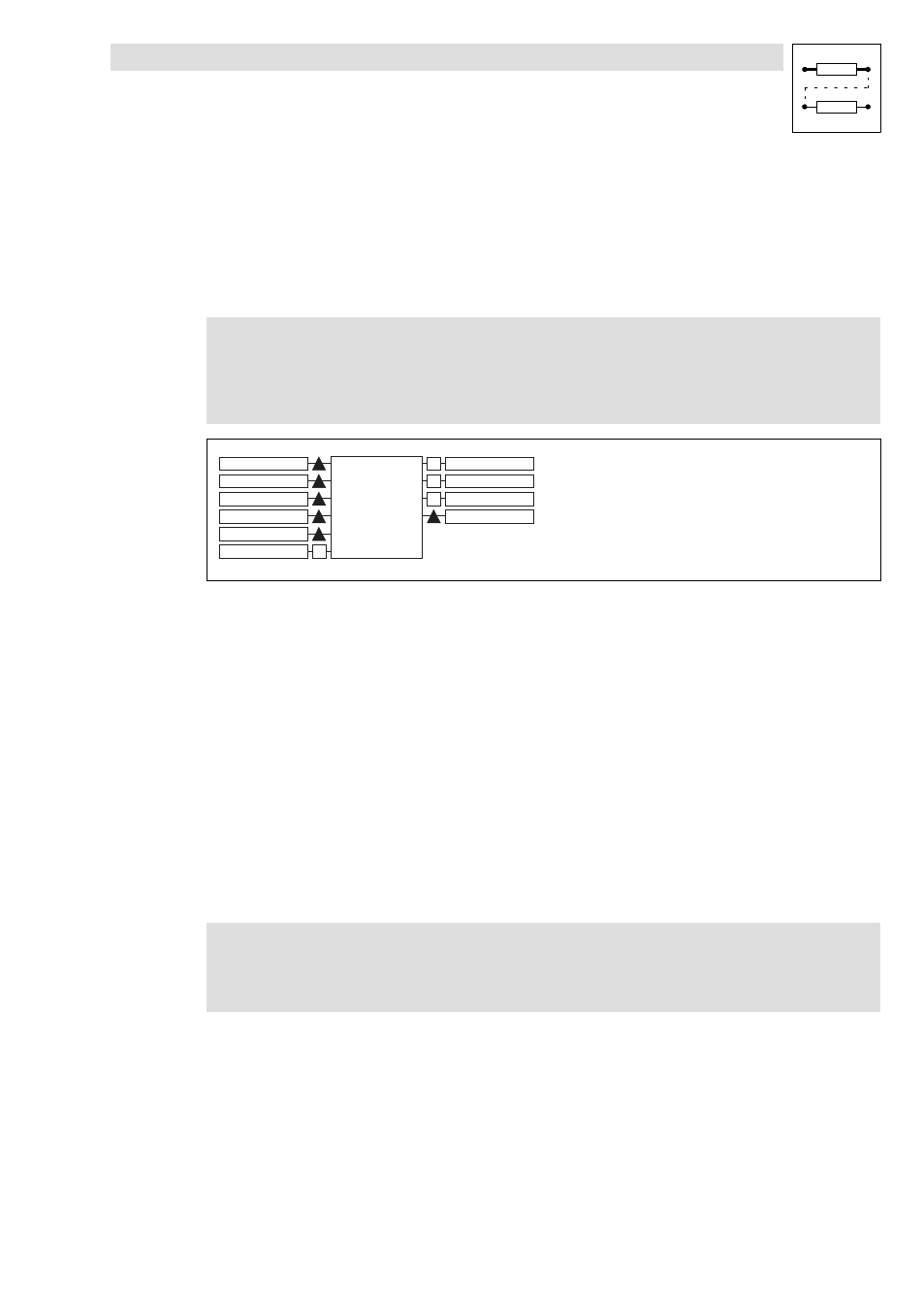
WELD1
LEN-C
XIN
LEN-O
LEN
TIME
ON
DIR-ERR
XOUT
T-ERR
BREAK
CDATA-XIN
DIGOUT4
0
fb_weld1_1
Fig. 3−261
Connection of WELD1 for power−controlled welding bar
WELD1−TIME
At WELD1−TIME, you must set a higher value than the actual welding time will be. Only then the
function block reacts to the input WELD1−BREAK.
The motion control is also ensured for very high values at WEDL1−TIME, even if no abort is
requested (WELD1−BREAK = HIGH). The function block behaves as if a welding time error
(WELD1−T−ERR) has occured.
0
WELD1−BREAK is triggered by the external control, e.g. via input terminal (X5/Ex)
3.2.102.3
Profile data selection
Phase 1
Start position:
l
X0 = 0 (master value) and Y0 = waiting position of the welding bar
End position
l
X1 = WELD1−LEN−C (time until the welding bar contacts the material)
l
Y1 = Welding bar in welding position (= start position of phase 2)
)
Note!
The slope of the profile should be dimensioned to the max. possible acceleration of
the welding drive at max. line speed.
Phase 2
The drive is kept in the welding position for the time set at WELD1−TIME. For this purpose, a waiting
phase (standstill phase) is automatically set at the transition from section 1 to section 2
(independently of the line speed). The waiting phase is not set when the profile data is created.
Phase 3
The end position must be selected such that the max. permissible acceleration of the welding drive
at max. line speed will not be exceeded (see also description of phase 1).