Function library, Function blocks – Lenze EVS9332xK User Manual
Page 282
Function library
Function blocks
3.2.78
Phase integrator (PHINT5)
3−254
l
EDSVS9332K−EXT EN 4.0
3.2.78.5
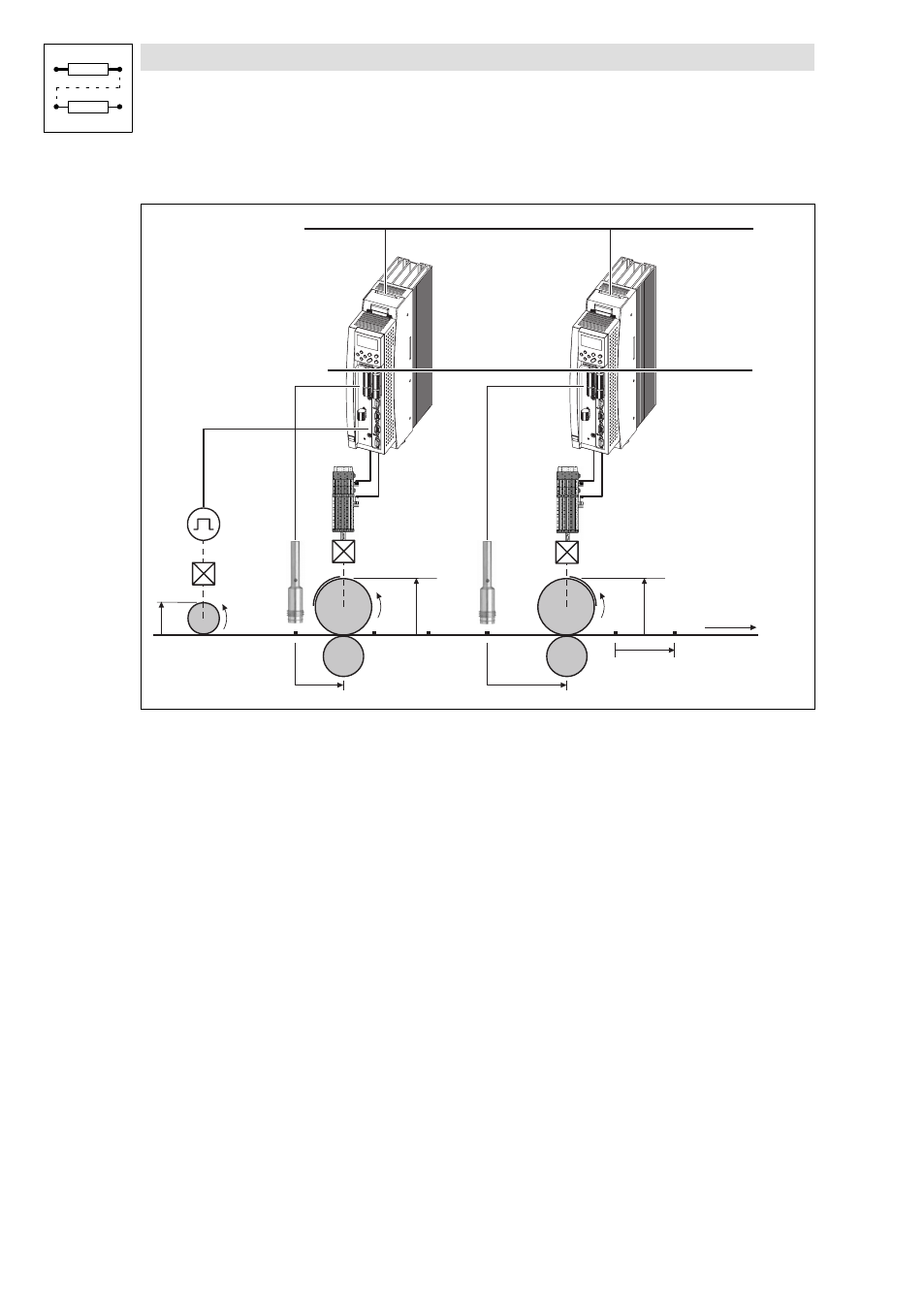
Example of a mark synchronisation
L
L
3 AC / PE / xxx V / xx HZ
i1
v1
d1
v2
v3
d2
d3
a2
a3
i2
i3
1
0
fb_phint5_1
Fig. 3−206
Principle of the mark synchronisation
0
Transmission of the master angle via system bus (CAN) or digital frequency
1
Register
v1
Speed of the material path
v2, v3
Speed of the material path ± correction
d1, d2, d3
Roller diameters
a2, a3
Distance of the touch probe sensor to the zero point
i1, i2, i3
Gearbox
l
At input PHINT5−TP−POS the distance of the touch probe sensor to the zero point of the
integrator has to be set (a2, a3)
– The value has to be between 0 and the value at PHINT5−H−VALUE.
l
When the touch probe signal occurs, the deviation between the value of the integrator and the
value at PHINT5−TP−POS is determined, is output at PHINT5−X−DIFF, and is compensated via
the mode set in C1740.