Configuring the triton voip board – AltiGen MAXCS 7.0 Update 1 ACM Administration User Manual
Page 128
Chapter 11: Board Configuration
112
MaxCS 7.5 Administration Manual
Configuring the Triton Analog Trunk LS/GS and LS Boards
The Triton Analog Trunk board is a long form factor PCI telephony card that supports 8 or 12 trunks. The 8 port
card supports only loop start (LS). The 12 port card is available in two models; loop start/ground start (LS/GS)
and LS. Both models have the same features regarding LS. The LS/GS board is required when ground start
trunks may be required.
Double-click the board in the Boards window to open the Board Configuration window, similar to (see
Figure
110). See attribute descriptions below (see Figure
58). Note the following additional infor-
mation:
•
Double-clicking a channel in the Channel Mapping List opens a channel configuration dialog box. See
“Triton Analog Station Line Properties” on page 181.
•
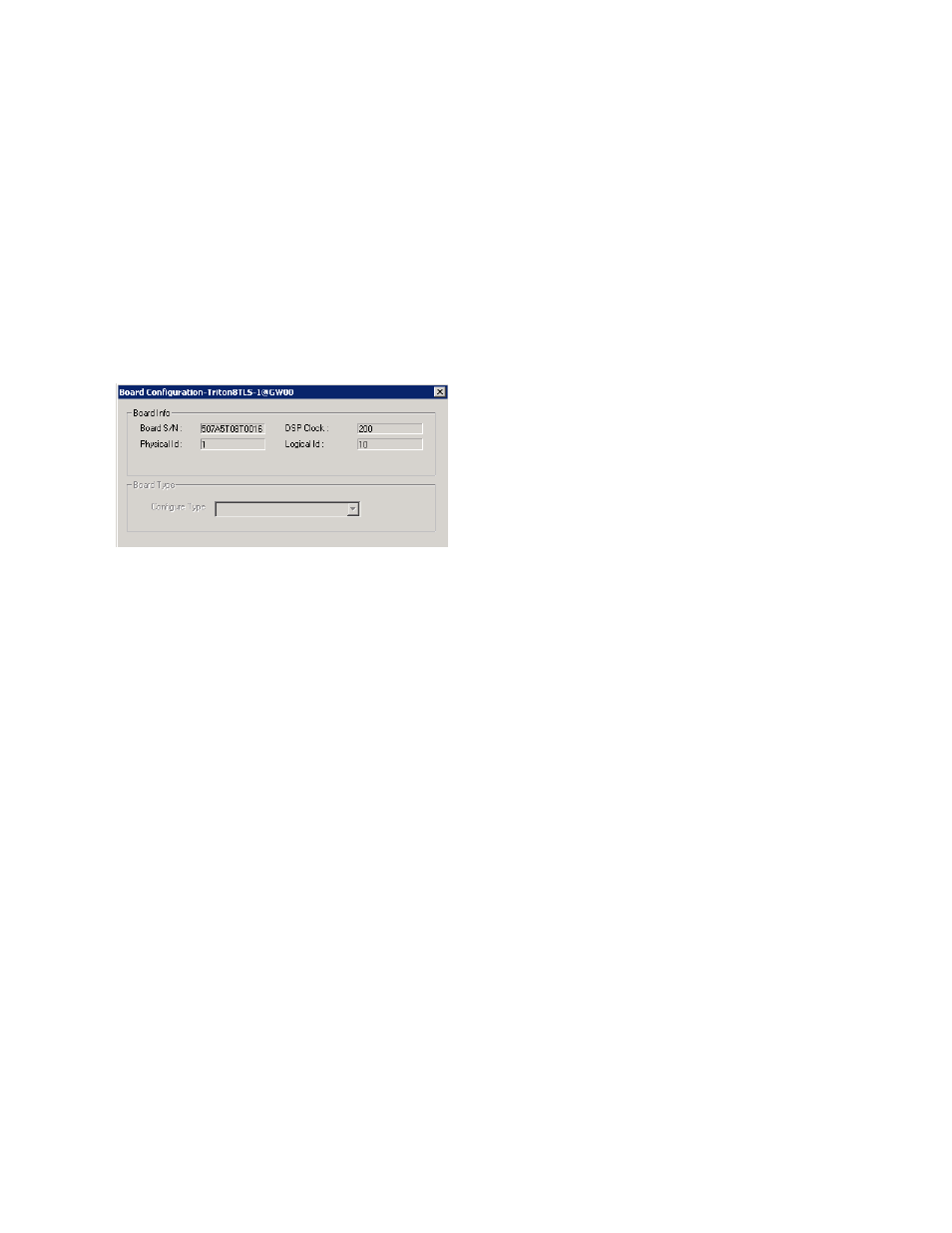
Clicking the Board Configuration button opens the following dialog box that displays the board’s serial
number, DSP clock, physical and logical IDs.
Figure 60.
Board Configuration dialog box
Configuring the Triton VoIP Board
It is strongly recommended that system administrators review the “Network Configuration Guidelines for VoIP”
on page 299 before setting up VoIP features.
VoIP for MAXCS runs on SIP protocols that allow voice calls to be made through an IP network. It includes an
integrated VoIP gateway to convert voice calls into IP packets and transmit them through the IP network.
MAXCS VoIP uses DSP engines residing on the Triton VoIP board to perform the voice coding/decoding
functions needed for SIP devices.
The Triton VoIP board can be configured as a 12-port G.711/G.723.1/G.729AB or 30-port G.711 board.
For limitations on configuring Triton VoIP boards and ports see AltiGen’s Telephony Hardware Manual.
To configure the board,
Double-click the TritonIP board in the Boards window to open the Board Configuration window, similar to
(see Figure
110). See attribute descriptions below (see Figure
Note the following additional information:
•
Clicking the Board Configuration button opens a window that displays the board serial number, DSP
clock, and physical and logical IDs. The list in the Configure Type field lets you select between a 12-port
G.711/G.723/G.729 configuration and a 30-port G.711 configuration.