Operation procedure – H3C Technologies H3C Intelligent Management Center User Manual
Page 218
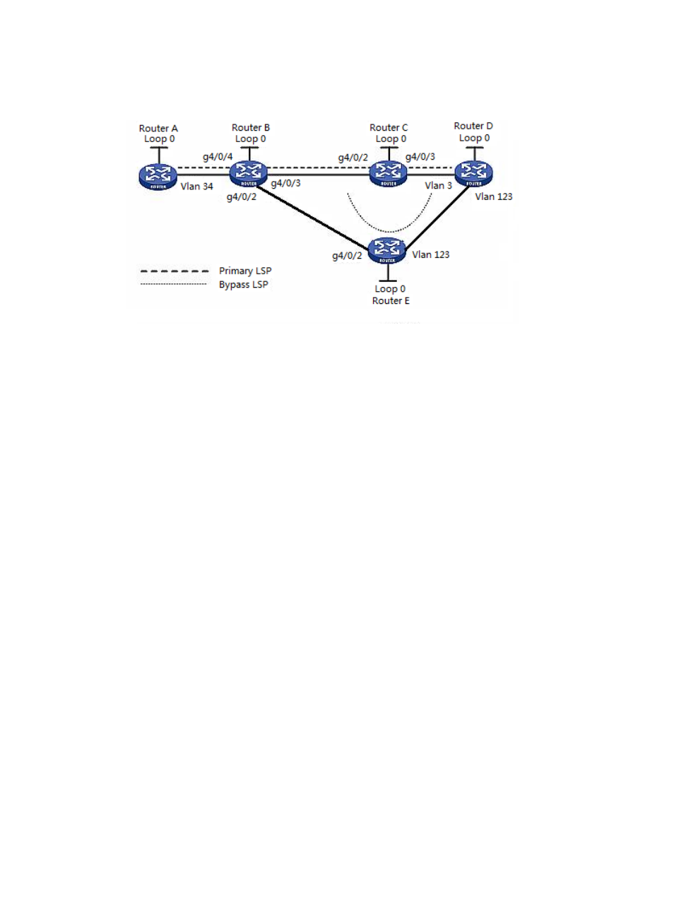
Figure 93 Usage scenario 5
In this scenario, you should create the primary tunnel through a dynamic signaling protocol. The primary
tunnel path is Router A —> Router B —> Router C —> Router D. In this tunnel, the link between Router
B and Router D needs to transmit important service data. Therefore it is required to protect the link's node
Router C. You should also create the bypass tunnel using a dynamic signaling protocol. The bypass
tunnel path is Router B —> Router E —> Router D. Once the link between Router B and Router D fails (for
example, Router C cannot be pinged on the network), the path will change to Router A —> Router B —>
Router E —> Router D.
•
Router A—Device name is H3C-1; Device IP is 172.10.0.70; LSR ID address is 3.3.3.70; address of
VLAN 34 (VLAN-interface 34) is 2.2.4.167.
•
Router B—Device name is H3C; Device IP is 172.10.0.82; LSR ID address is 3.3.3.82; address of
g4/0/4 (GigabitEthernet 4/0/4) is 2.2.4.4; address of g4/0/2 (GigabitEthernet 4/0/2) is
11.11.13.165; address of g4/0/3 (GigabitEthernet 4/0/3) is 1.1.1.165.
•
Router C—Device name is H3C-3; Device IP is 172.10.0.88; LSR ID address is 3.3.3.88; address of
g4/0/2 (GigabitEthernet 4/0/2) is 11.11.13.166; address of g4/0/3 (GigabitEthernet 4/0/3) is
11.11.12.166.
•
Router D—Device name is H3C-2; Device IP is 172.10.0.91; LSR ID address is 3.3.3.91; address of
VLAN 3 (VLAN-interface 3) is 1.1.1.164; address of VLAN 123 (VLAN-interface 123) is 11.11.12.164.
•
Router E—Device name is H3C-4; Device IP is 172.10.0.92; LSR ID address is 3.3.3.92; address of
VLAN 123 (VLAN-interface 123) is 11.11.12.133; address of g4/0/2 (GigabitEthernet 4/0/2) is
11.11.13.177.
Operation procedure
Import Router A, Router B, Router C, Router D and Router E into MPLS TE Management.
To configure an explicit path for the primary tunnel:
1.
Click Service > MPLS TE Manager > Explicit Path Mng from the tabular navigation system on the
top of the IMC main page.
208