Operation procedure – H3C Technologies H3C Intelligent Management Center User Manual
Page 197
In this scenario, the main factor that causes network congestions is the network load imbalance. To
ensure that important services can be smoothly transmitted along Router A —> Router B —> Router C,
you should import Router A, Router B and Router C into MPLS TE Management, configure an MPLS TE
tunnel using static CR-LSP, and then introduce traffic to it. Router A works as the ingress device, Router B
works as the transit device and Router C works as the egress device.
•
Router A—Device name is H3C-1; Device IP is 172.10.0.70; LSR ID address is 3.3.3.70; address of
VLAN-interface 34 is 2.2.4.167.
•
Router B—Device name is H3C; Device IP is 172.10.0.82; LSR ID address is 3.3.3.82; address of
GigabitEthernet 4/0/4 is 2.2.4.4; address of GigabitEthernet 4/0/2 is 11.11.13.165.
•
Router C—Device name is H3C-3; Device IP is 172.10.0.88; LSR ID is 3.3.3.88; address of
GigabitEthernet 4/0/2 is 11.11.13.166.
Operation procedure
Import Router A, Router B and Router C into MPLS TE Management.
To configure an MPLS TE tunnel using static CR-LSP:
1.
Click Service > MPLS TE Manager > MPLS TE Tunnel Mng from the tabular navigation system on the
top of the IMC main page.
2.
In the MPLS TE Tunnel Query List section, click Add.
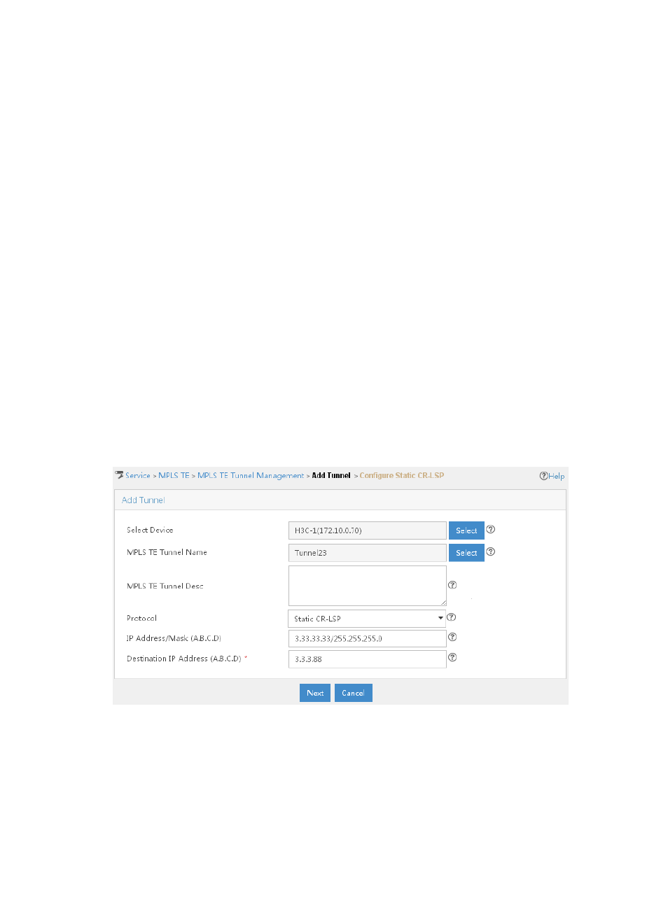
The Configure Static CR-LSP page appears, as shown in
.
Figure 60 Usage scenario 1 — Add Tunnel page
3.
Specify the configuration information for the static CR-LSP.
a.
Select Router A as the ingress device for the MPLS TE tunnel. Click Select next to Select Device.
On the Select Device page, specify part or the entire name of Router A, and then click Query.
Devices that match the description appear in the Device Query List section of the page. Select
Router A, and then click OK.
187