Stateful failover configuration example, Network requirements, Figure 655 – H3C Technologies H3C WX3000E Series Wireless Switches User Manual
Page 627: Table 209
611
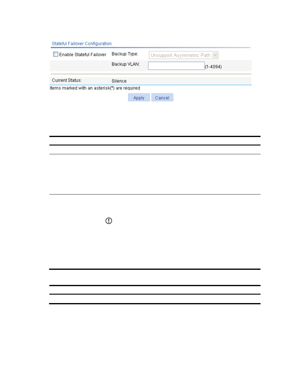
Figure 655 Stateful failover configuration page
3.
Configure stateful failover parameters at the upper part of the page as described in
4.
Click Apply.
Table 208 Configuration items
Item Description
Enable Stateful Failover
Enable/disable the stateful failover feature.
Backup Type
Select whether to support asymmetric path.
•
Unsupport Asymmetric Path. In this mode, sessions enter and leave the internal
network through one device. The two devices work in the active/standby mode.
•
Support Asymmetric Path. In this mode, sessions enter and leave the internal
network through different devices to achieve load sharing. The two devices
work in the active/active mode.
Backup VLAN
Set the backup VLAN.
After a VLAN is configured as a backup VLAN, the interface(s) in the VLAN is used
to transmit stateful failover packets.
IMPORTANT:
•
A device uses VLAN tag+protocol number to identify stateful failover packets,
and broadcasts stateful failover packets to the peer within the backup VLAN.
Therefore, H3C does not recommend that you configure other services (such as
voice VLAN) for a backup VLAN to avoid impact on the operation of stateful
failover.
•
An interface added to the backup VLAN can transmit other packets besides
stateful failover packets.
Table 209 Field description
Field Description
Current Status
Displays the failover state of the device.
Stateful failover configuration example
Network requirements
In
, the IP address of VLAN-interface 1 on AC 1 is 8.190.1.60/16, and that on AC 2 is
8.190.1.61/16. The client and AP each obtain an IP address from the DHCP server at 8.190.0.13/16, and