Figure 594, Client 1 is assoc – H3C Technologies H3C WX3000E Series Wireless Switches User Manual
Page 579

563
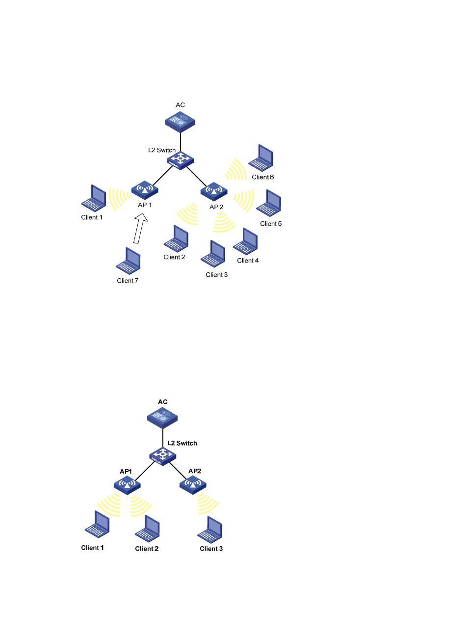
of sessions is 5 and the maximum session gap is 4. Then, Client 7 sends an association request to
AP 2. The maximum session threshold and session gap have been reached on AP 2, so it rejects
the request. At last, Client 7 associates with AP 1.
Figure 594 Network diagram for session-mode load balancing
•
Traffic mode load-balancing
Traffic snapshot is considered for traffic mode load balancing.
As shown in
, Client 1 and Client 2 that run 802.11g are associated with AP 1. The AC
has traffic-mode load balancing configured: the maximum traffic threshold is 10% and the
maximum traffic gap is 20%. Then, Client 3 wants to access the WLAN through AP 1. The
maximum traffic threshold and traffic gap (between AP 1 and AP 2) have been reached on AP 1,
so it rejects the request. At last, Client 3 associates with AP 2.
Figure 595 Network diagram for traffic-mode load balancing
