Enabling a radio – H3C Technologies H3C WX3000E Series Wireless Switches User Manual
Page 265
249
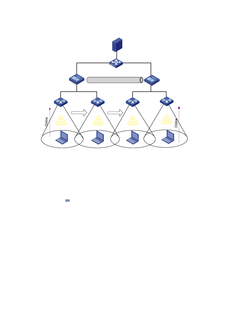
Figure 234 Schematic diagram for WLAN support for AP-based access VLAN recognition
As shown in
, Client 1 goes online through AP 1 and belongs to VLAN 3. When Client 1
roams within an AC or between ACs, Client 1 always belongs to VLAN 3. When Client 1 roams between
ACs, if FA, that is, AC 2, has VLAN-interface 3, AC 2 forwards packets from Client 1. Otherwise, packets
from Client 1 are sent to HA (AC 1) through the data tunnel and then HA forwards these packets.
Client 2 goes online through AP 4 and belongs to VLAN 2. That is, a client going online through a
different AP is assigned to a different VLAN.
1.
Select Wireless Service > Access Service from the navigation tree.
2.
Click the
icon corresponding to the target wireless service to enter the AP radio setup page, as
.
3.
Select the box corresponding to the AP radio mode to be bound.
4.
Enter the VLAN to be bound in the Binding VLAN field.
5.
Click Bind.
Enabling a radio
1.
Select Radio > Radio from the navigation tree.
RADIUS server
AC 1
AC 2
IACTP tunnel
AP 1
VLAN 2
VLAN 3
Client 1
AP 2
Client 1
AP 3
Client 1
AP 4
Client 2
Intra AC roaming
Inter AC roaming
HA
FA
VLAN 3
VLAN 3