Standard ladder logic elements, continued – Schneider Electric Processor Adapter User Manual
Page 407
Ladder Logic Elements and Instructions
870 USE 101 10 V.2
407
Standard Ladder Logic Elements, Continued
Standard Ladder
Logic
Instructions
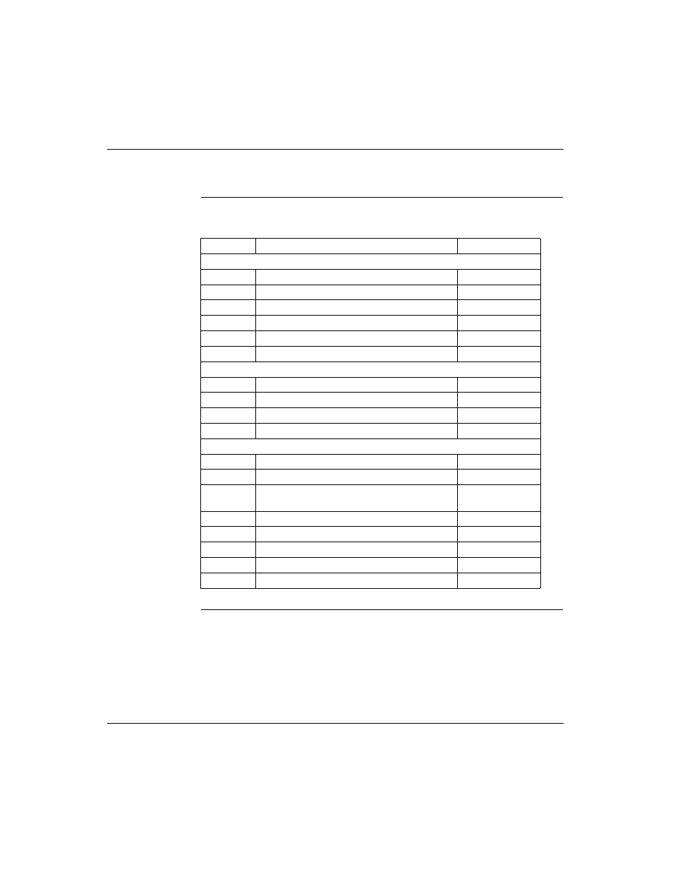
The table below provides standard ladder logic instructions and their meaning.
Continued on next page
Symbol
Meaning
Nodes Consumed
Counter and Timer Instructions
UCTR
Counts up from 0 to a preset value
2
DCTR
Counts down from a preset value to 0
2
T1.0
Timer that increments in seconds
2
T0.1
Timer that increments in tenths of a second
2
T.01
Timer that increments in hundredths of a second
2
T1MS
A timer that increments in milliseconds
3
Integer Math Instructions
ADD
Adds top node value to middle node value
3
SUB
Subtracts middle node value from top node value
3
MUL
Multiplies top node value by middle node value
3
DIV
Divides top node value by middle node value
3
DX Move Instructions
R
∀
T
Moves register values to a table
3
T
∀
R
Moves specified table values to a register
3
T
∀
T
Moves a specified set of values from one table to
another table
3
BLKM
Moves a specified block of data
3
FIN
Specifies first-entry in a FIFO queue
3
FOUT
Specifies first-entry out of a FIFO queue
3
SRCH
Performs a table search
3
STAT
CROSS REF
1