Schneider Electric Processor Adapter User Manual
Page 196
Using the Modbus Plus Ports
196
870 USE 101 10 V.2
Pinouts and Wiring Illustrations for Modbus Plus Networks, Continued
Modbus Plus
Connector “T”
(DB9 Base)
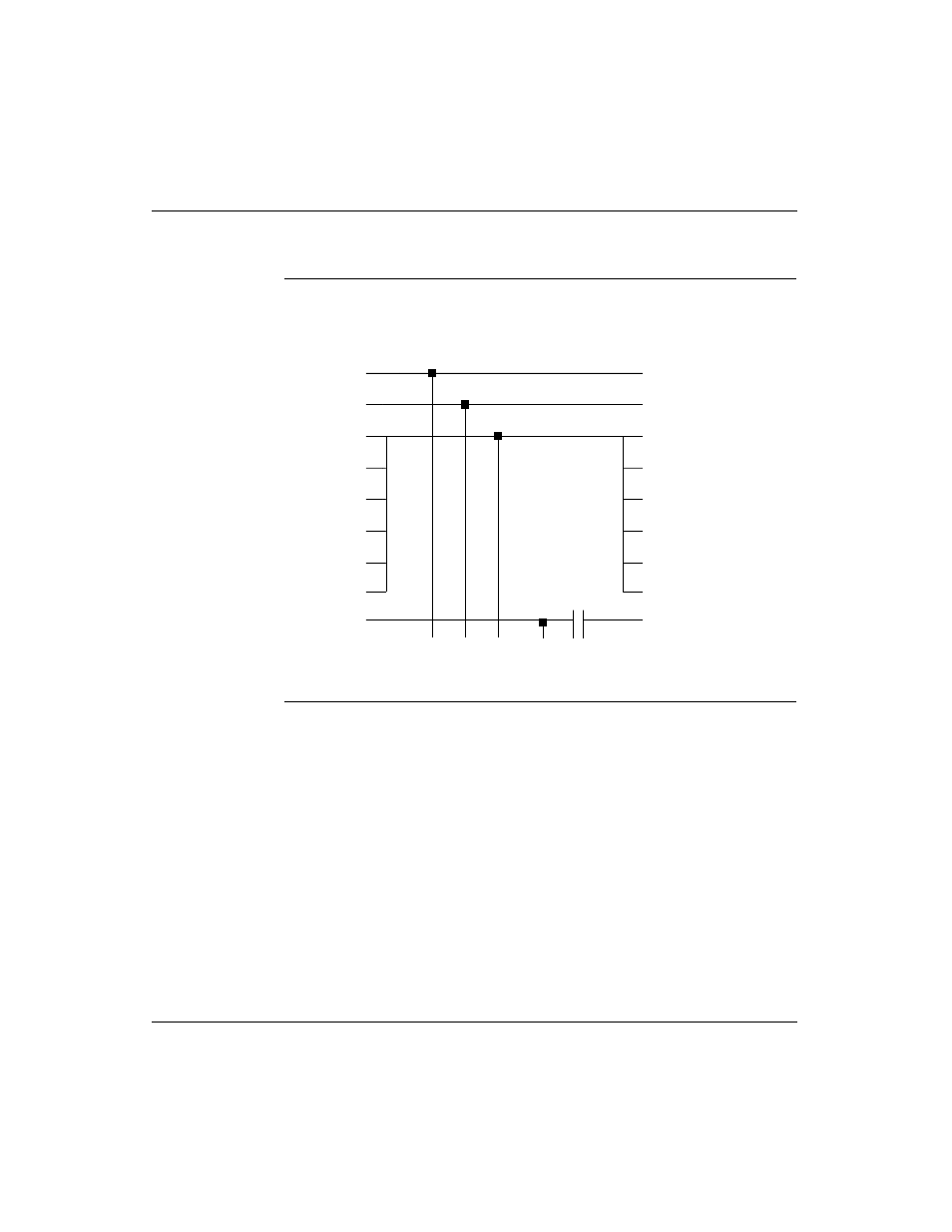
The following illustration shows the pinout for the Modbus Plus Connector “T” (DB9
base):
Continued on next page
RJ45 Shielded Connector
RJ45 Shielded Connector
TX+ 1
Shield 3
2 TX-
3 Shield
4
5
6
7
8
4
5
6
7
8
Shell
Shell
.1 uF
500 V
1
2
3
DB9 Connector
1 TX+
TX- 2
TX+ TX-
Shield
Shell