Completing the configuration – Schneider Electric Processor Adapter User Manual
Page 302
Using Peer Cop with Modsoft
302
870 USE 101 10 V.2
Completing the Configuration
Overview
To complete the configuration of the supervisory computer at Modbus Plus address
1, create a Peer Cop screen that accesses the CPU at address 3 and defines the
references for that CPU.
Accessing
Node 3
Using the AddNode command, create a new Peer Cop screen with a Link setting of
1 and a Node setting of 3.
Specifying
References for
Node 3
We know that this M1 CPU sends 16 words of specific output to the supervisor and
receive seven words of global data from the supervisor. Follow the steps in the
table below to define the registers that the supervisor will transmit to and receive
from the M1 CPU at Modbus Plus address 3.
Step
Action
1
In the REFERENCE column of the SPECIFIC INPUT field, type the value 400020,
the first register which will receive the input. Push
2
Type the value 16 in the LEN column of the SPECIFIC INPUT field, indicating the
number of registers that will be received. Push
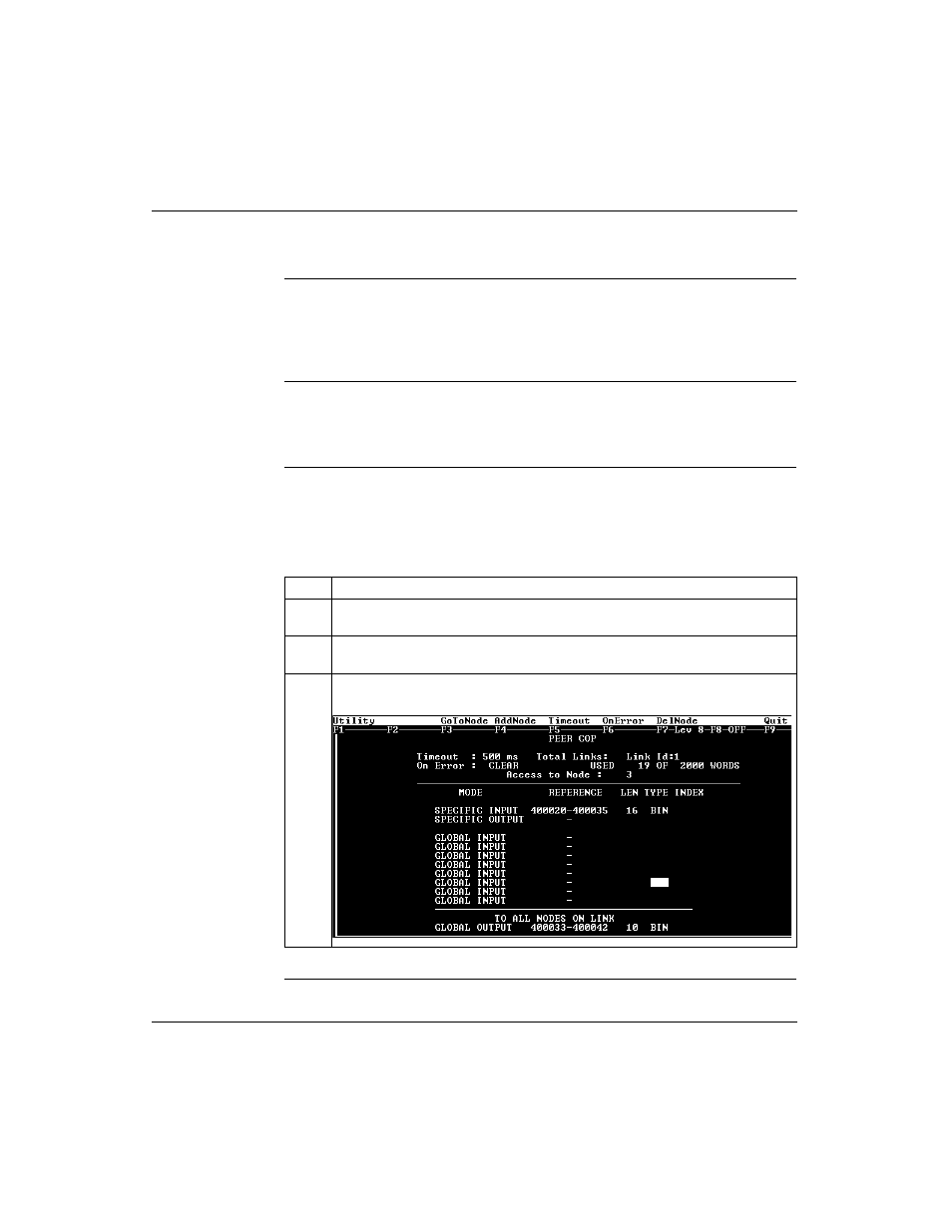
3
The GLOBAL OUTPUT fields should already be complete, since you filled them out
for node 2. The completed Peer Cop screen should look like this: