8 command source, Issue 01/06 parameter description – Siemens 440 User Manual
Page 75
Issue 01/06
Parameter Description
MICROMASTER 440 Parameter List
6SE6400-5BB00-0BP0
75
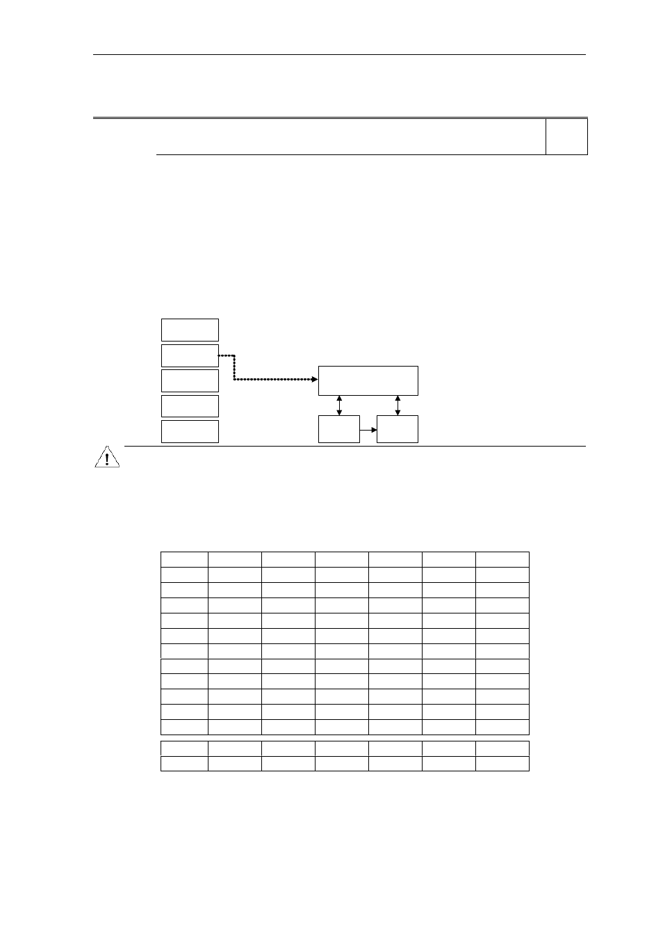
3.8 Command
source
P0700[3]
Selection of command source
Min: 0
CStat:
CT
Datatype: U16 Unit:
-
Def:
2
P-Group: COMMANDS
Active: first confirm
QuickComm.: Yes Max: 6
Selects digital command source.
Possible Settings:
0
Factory default setting
1 BOP
(keypad)
2 Terminal
4
USS on BOP link
5
USS on COM link
6
CB on COM link
Index:
P0700[0] : 1st. Command data set (CDS)
P0700[1] : 2nd. Command data set (CDS)
P0700[2] : 3rd. Command data set (CDS)
Example:
Changing form P0700 = 1 to P0700 = 2 sets all digital inputs to default settings.
BOP
USS
BOP link
USS
COM link
P0700 = 2
Terminals
CB
COM link
Sequence control
Setpoint
channel
Motor
control
Caution:
Be aware, by changing of parameter P0700 all BI parameters are reset to the default value or modified as
listed in the table below.
If the Inverter is being controlled via the AOP, select USS (with the corresponding interface) for the
Command Source. If the AOP is connected to the BOP-Link Interface, then set Parameter P0700 to the
value 4 (P0700 = 4).
Note:
Changing this parameter sets (to default) all settings on item selected (see table).
P0700 = 0
P0700 = 1
P0700 = 2
P0700 = 4
P0700 = 5
P0700 = 6
P0701
1
0
1
0
0
0
P0702
12
0
12
0
0
0
P0703
9
9
9
9
9
9
P0704
15
15
15
15
15
15
P0705
15
15
15
15
15
15
P0706
15
15
15
15
15
15
P0707
0
0
0
0
0
0
P0708
0
0
0
0
0
0
P0731
52.3
52.3
52.3
52.3
52.3
52.3
P0732
52.7
52.7
52.7
52.7
52.7
52.7
P0733
0.0
0.0
0.0
0.0
0.0
0.0
P0800
0.0
0.0
0.0
0.0
0.0
0.0
P0801
0.0
0.0
0.0
0.0
0.0
0.0
Level
1