Issue 01/06 function diagrams, Ex ter nal interfaces mi crom as te r 4 40, Uss on co m l ink , rec ei vi ng – Siemens 440 User Manual
Page 269
Issue 01/06
Function Diagrams
MICROMASTER 440 Parameter List
6SE6400-5BB00-0BP0
269
- 2600
-
F
unc
tion diagram
8
7
6
5
4
3
2
1
2600
_USSonC
OM.
vs
d
Ex
ter
nal
Interfaces
MI
CROM
AS
TE
R 4
40
16
.0
1.
2006
V2.
1
USS
on CO
M l
ink
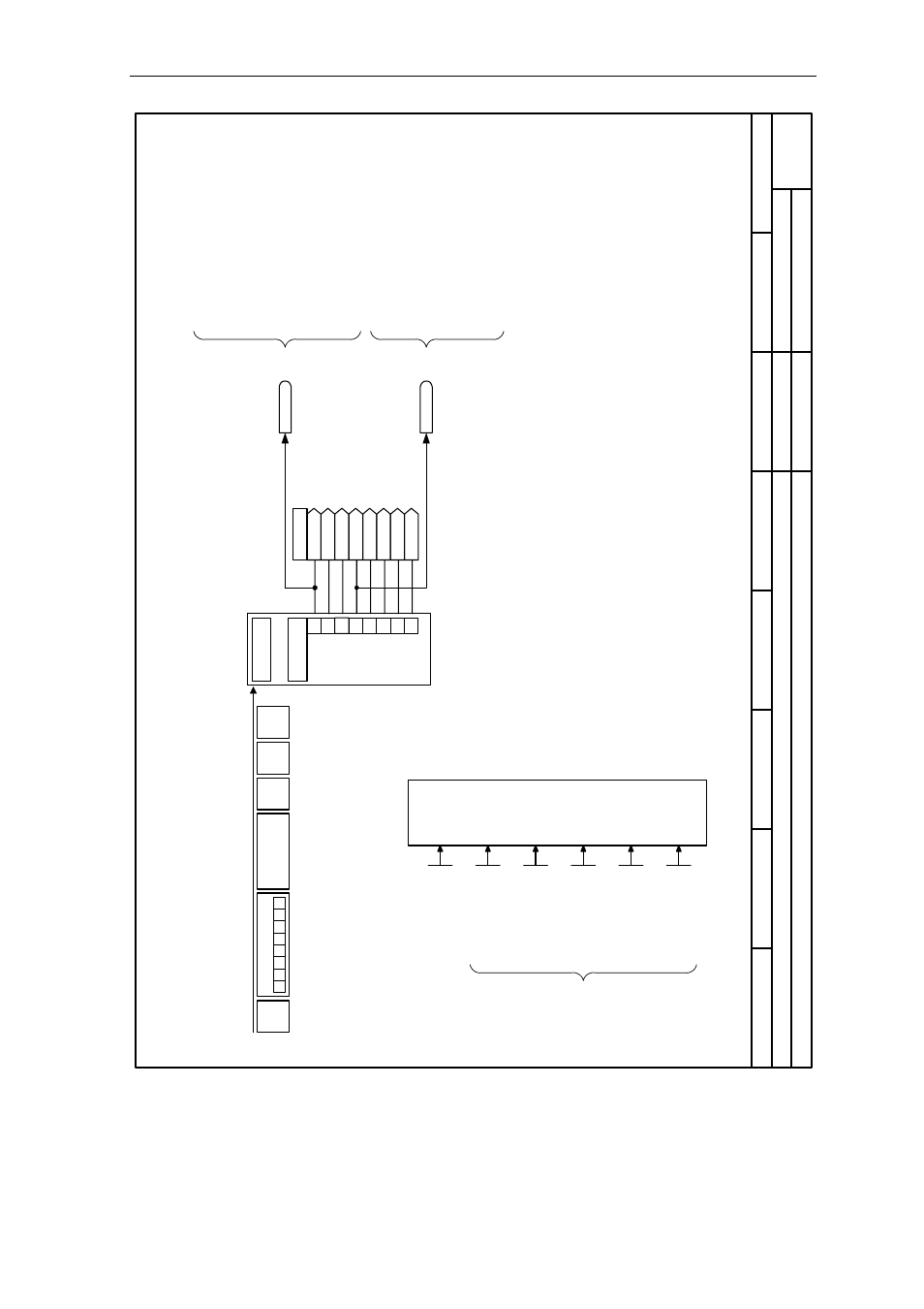
, Rec
ei
vi
ng
All
par
ameter
s:
Index =
0
=>
C
O
M
li
nk
PKW
PZ
D
1
[0]
r2018
[1]
[2]
[3]
2
3
4
5
6
7
0
[4]
[5]
[6]
[7]
USS ba
udrate
4 ..
. 12
P
2
010 [2] (
6)
BO
: Ctr
lWd
1 <-
CO
M
r2036
BO
: Ctr
lWd
2 <-
CO
M
r2037
STX
LG
E
ADR
BCC
PZD
PKW
0
7
6
5
4
3
2
1
Recei
ve
tele
gram
Rx
D
Rec
ei
ve
USS
co
nfigu
rati
on
C
hange pa
r. via
0 .
.. 15
P092
7 (15)
U
S
S a
ddress
0 ..
. 31
P
2
011 [2] (
0)
USS PKW l
ength
0
... 127
P2013 [2]
(127)
U
S
S
P
Z
D
length
0 ... 8
P201
2 [2] (2
)
USS tel
egr
am T
_off
0 .
.. 65535 [m
s]
P2014 [2]
(0)
Bit3 =
1
No
te
:
Bit 10 must be set in the
fi
rs
t PZD w
ord
of the
tel
egr
am re
ce
iv
ed via
USS so that the conver
ter
wi
ll a
ccept the
process data as
bei
ng val
id.
For
thi
s r
eason, the contr
ol
wo
rd 1 m
us
t b
e tran
sf
er
red
to the convert
er
in the first PZ
D wo
rd.
Bi
t00 ON/OF
F
1
Bi
t01 OFF
2: El
ectri
ca
l stop
Bit
02
OF
F3
: Fa
st
s
top
Bi
t03 Pul
se enabl
e
Bi
t04 RF
G enabl
e
Bi
t05 RF
G start
Bi
t06 Setpoi
nt en
able
Bi
t07 F
aul
t ac
know
le
dge
Bi
t08 JOG
r
ight
Bi
t09 JOG
le
ft
Bi
t10 Co
ntrol
fr
om PLC
Bi
t11 Re
ve
rs
e (setpoi
nt i
nversi
on)
Bi
t13 Moto
r pote
ntiom
eter M
O
P u
p
Bi
t14 Moto
r pote
ntiom
eter M
O
P d
own
Bi
t15 CD
S Bit
0 (Local
/Rem
ote)
Bi
t00 F
ixed fr
equency Bit
0
Bi
t01 F
ixed fr
equency Bit
1
Bi
t02 F
ixed fr
equency Bit
2
Bi
t03 F
ixed fr
equency Bit
3
Bit04 Dr
iv
e d
ata set (D
DS)
B
it 0
Bit05 Dr
iv
e d
ata set (D
DS)
B
it 1
Bi
t08 PID
enabl
ed
Bi
t09 DC
bra
ke e
nabl
ed
Bi
t11 Dr
oop
Bi
t12 T
orque
c
on
trol
Bi
t13 Extern
al fa
ult 1
Bi
t15 Co
mmand da
ta set (C
DS) Bi
t 1