Siemens 440 User Manual
Page 214
Parameter Description
Issue 01/06
MICROMASTER 440 Parameter List
214
6SE6400-5BB00-0BP0
P2166[3]
Delay time ramp up completed
Min: 0
CStat:
CUT
Datatype: U16 Unit:
ms
Def:
10
P-Group: ALARMS
Active: Immediately
QuickComm.: No
Max: 10000
Delay time for signal that indicates completion of ramp-up.
Index:
P2166[0] : 1st. Drive data set (DDS)
P2166[1] : 2nd. Drive data set (DDS)
P2166[2] : 3rd. Drive data set (DDS)
Details:
See diagram in P2174.
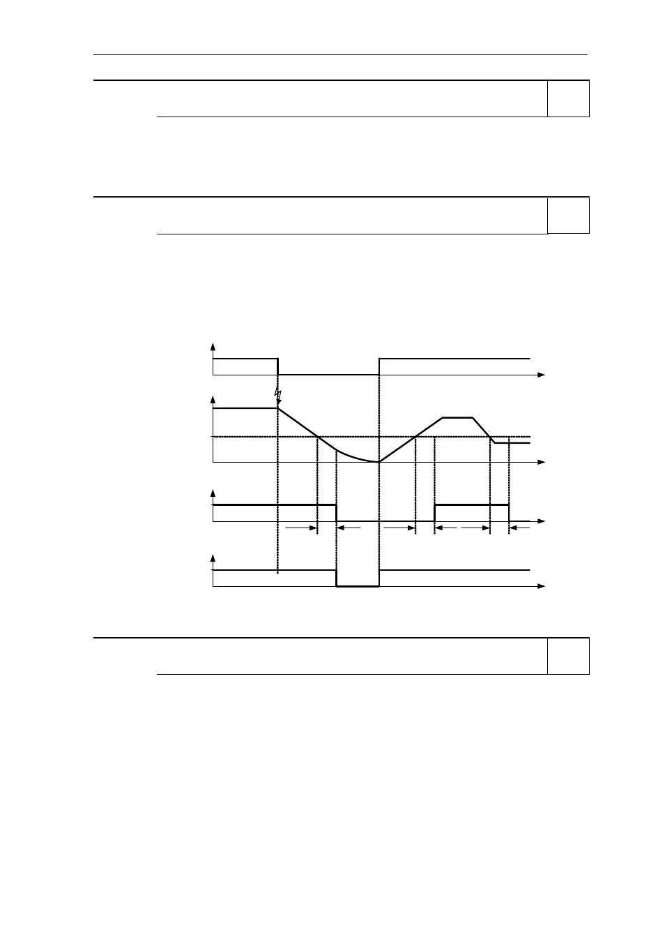
P2167[3]
Switch-off frequency f_off
Min: 0.00
CStat:
CUT
Datatype: Float Unit:
Hz
Def:
1.00
P-Group: ALARMS
Active: Immediately
QuickComm.: No
Max: 10.00
Defines the threshold of the monitoring function |f_act| <= P2167 (f_off).
P2167 influences following functions:
-
If the actual frequency falls below this threshold and the time delay has expired, bit 1 in status word 2
(r0053) is reset.
-
If a OFF1 or OFF3 was applied and bit 1 is reset the inverter will disable the pulse (OFF2).
Restriction:
-
The monitoring function |f_act| <= P2167 (f_off) is not updated and pulses are not disabled, if motor
holding brake (MHB, P1215 = 1) is enabled.
|f|
t
0
1
P2168
t
t
r0053
Bit 01
OFF2
P2167
Active
Inactive
act
f
P2168
P2168
OFF1/OFF3
|f_act| > P2167
OFF1/OFF3
ON
t
Index:
P2167[0] : 1st. Drive data set (DDS)
P2167[1] : 2nd. Drive data set (DDS)
P2167[2] : 3rd. Drive data set (DDS)
P2168[3]
Delay time T_off
Min: 0
CStat:
CUT
Datatype: U16 Unit:
ms
Def:
10
P-Group: ALARMS
Active: Immediately
QuickComm.: No
Max: 10000
Defines time for which the inverter may operate below switch-off frequency (P2167) before switch off
occurs.
Index:
P2168[0] : 1st. Drive data set (DDS)
P2168[1] : 2nd. Drive data set (DDS)
P2168[2] : 3rd. Drive data set (DDS)
Dependency:
Active if holding brake (P1215) not parameterized.
Details:
See diagram in P2167 (switch-off frequency)
Level
2
Level
3
Level
3