5 speed encoder – Siemens 440 User Manual
Page 67
Issue 01/06
Parameter Description
MICROMASTER 440 Parameter List
6SE6400-5BB00-0BP0
67
3.5 Speed
encoder
P0400[3]
Select encoder type
Min: 0
CStat:
CT
Datatype: U16 Unit:
-
Def:
0
P-Group: ENCODER
Active: Immediately
QuickComm.: No
Max: 2
Selects encoder type (number of encoder channels).
Possible Settings:
0 Disabled
1
Single channel encoder
2
Quadrature encoder without zero pulse
Index:
P0400[0] : 1st. Drive data set (DDS)
P0400[1] : 2nd. Drive data set (DDS)
P0400[2] : 3rd. Drive data set (DDS)
Dependency:
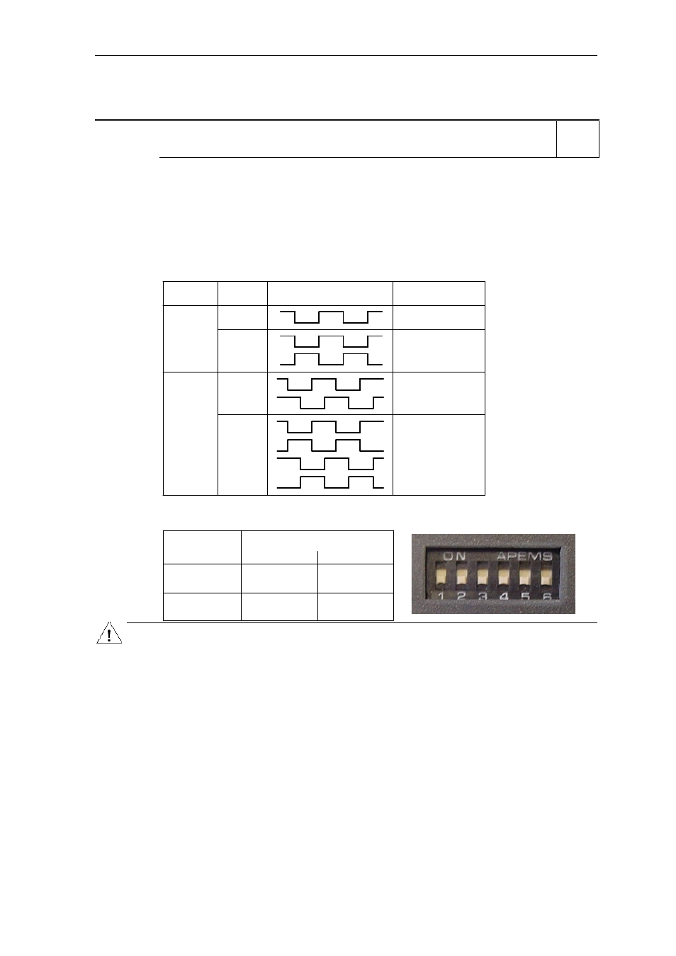
Following table displays the setting of P0400 which depends upon the number of encoder channels:
Parameter
Terminal
Track
Encoder output
single ended
P0400 = 1
A
differential
A
AN
A
B
A
AN
B
BN
differential
P0400 = 2
single ended
Following table displays the setting the of the encoder DIPs on the encoder option modul which have to be
set depending on the encoder type (TTL, HTL) and encoder output:
Type
differential
TTL
HTL
111111
010101
101010
000000
single ended
Output
(e.g.
(e.g.
1XP8001-1)
1XP8001-2)
Caution:
When using Vector Control with encoder-feedback , the direction of rotation of the Encoder and Motor must
be the same. If this is not achieved, then the functional operation of the Vector Control will not be
guaranteed (positive instead of negative feedback). Extreme care must therefore be taken with respect to
the connection of the motor to the inverter as well as the correct connection of the encoder to the Encoder
module. Motor and Encoder must not be incorrectly wired up !
When commissioning Vector Control with encoder-feedback (VC), the drive should be configured for V/f
mode (see P1300) first. Run the drive and compare r0061 with r0021 that should agree in
- sign
and
-
magnitude (with a deviation of only a few percent).
Only if both criteria are fullfilled, change P1300 and select VC (P1300 = 21 or 23).
P0400 = 1 (single channel encoder) will only allow operation in one direction. If operation in both directions
is required, connect an encoder with 2 channels (A and B) and select setting 2. See the Operating
Instructions of the encoder module for more information.
Note:
Encoders with zero pulse can also be connected, but the zero pulse is not used in MM4.
The term "quadrature" in setting 2 refers to two periodic functions separated by a quarter cycle or 90
degrees.
Level
2