Function diagrams issue 01/06, Ex ter nal interfaces mi crom as te r 4 40 – Siemens 440 User Manual
Page 272
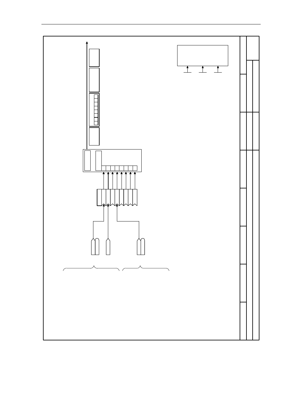
Function Diagrams
Issue 01/06
MICROMASTER 440 Parameter List
272
6SE6400-5BB00-0BP0
- 2710
-
F
unc
tion diagram
8
7
6
5
4
3
2
1
271
0_C
B
onCO
M
.v
sd
Ex
ter
nal
Interfaces
MI
CROM
AS
TE
R 4
40
16
.0
1.
2006
V2.
1
CB on
C
O
M l
ink,
T
rans
mitti
ng
PKW
PZD
1
2
3
4
5
6
7
0
T
ran
sm
it tel
egr
am
[0]
P2051
[2]
[3]
[4]
[1]
[5]
[6]
[7]
CO/BO: Act StatWd1
r0052
r0052
r0021
CO: f_a
ct filt 1 [Hz]
CO/BO: Act StatWd2
r0053
r0053
Tx
D
Bit
00 Dr
ive r
eady
Bit
01 Dr
ive r
eady to r
un
Bit
02 Dr
ive r
unni
ng
Bi
t03 Dr
iv
e fau
lt active
Bit
04 OFF
2 active
Bit
05 OFF
3 active
Bit
06 ON i
nhi
bit
ac
tive
Bit
07 Dr
ive w
arni
ng acti
ve
Bit
08 Devi
ati
on setpoi
nt / act. val
ue
Bit
09 PZD
control
Bit
10 Maxi
mum fr
equency reached
Bi
t11 War
ni
ng
: Motor
c
u
rre
nt
Bit
12 Motor
hol
di
ng br
ak
e
ac
tive
Bit
13 Motor
overl
oad
Bit
14 Motor
ru
ns
r
ight
Bit
15 Inverte
r over
load
Bit
00 DC
brake acti
ve
Bit
01 Act. freq
. r0021
>
P2167 (
f_off)
Bit
02 Act. freq
. r0021
>
P1080 (
f_mi
n)
Bit
03 Act. c
u
rr
ent r00
27 >
=
P21
70
Bit
04 Act. freq
. r0021
>
=
P215
5 (f_1
)
Bit
05 Act. freq
. r0021
<
P2155 (
f_1)
Bit
06 Act. freq
. r0021
>=
setpoi
nt
Bit
07 Act. Vdc r0026
< P2
172
Bit
08 Act. Vdc r0026
> P2
172
Tr
an
sm
it
Bit
09 Ram
ping
fini
shed
Bit
10 PID ou
tput r2
294 =
=
P2292 (
P
ID_mi
n)
Bit
11 PID ou
tput r2
294 =
=
P2291 (
P
ID_max)
Bit
14 Dow
nl
oad data set 0
from AOP
Bit
15 Dow
nl
oad data set 1
from AOP
C
B
tel. off time
0
... 65535 [
m
s]
P2040 (
20)
CB
confi
gur
ati
on
Cha
nge par
. via
0 ... 1
5
P0927 (15)
C
B
para
m
eter
0 ... 65535
P2041 [5]
(0)
B
it0 =
1
PZ
D
PKW
7
6
5
4
3
2
1
CB
-F
ra
m
e
C
B
-F
rame
0
No
te:
P2051[0] =
52
P2051[1] =
21
P2051[3] =
53
are defaul
t settin
gs