Parameter description issue 01/06, P2120 indication counter – Siemens 440 User Manual
Page 210
Parameter Description
Issue 01/06
MICROMASTER 440 Parameter List
210
6SE6400-5BB00-0BP0
Example:
P2115[0] = 13625
P2115[1] = 2579
P2115[2] = 516
The conversion into binary quantities (U16) results in the following bit pattern:
Seconds + minutes:
-
High byte (MSB) = 00110101 corresponding to the number 53, i.e. seconds 53
-
Low byte (LSB) = 00111001 corresponding to the number 57, i.e. minutes 57
Hours + days:
-
High byte (MSB) = 00001010 corresponding to the number 10, i.e. hours 10
-
Low byte (LSB) = 00010011 corresponding to the number 19, i.e. days 19
Months + year:
-
High byte (MSB) = 00000010 corresponding to the number 2, i.e. months 2
-
Low byte (LSB) = 00000100 corresponding to the number 4, i.e. years 4
This means that the real time displayed in P2115 is 19.02.2004, 10:57:53.
P2120 Indication
counter
Min: 0
CStat:
CUT
Datatype: U16 Unit:
-
Def:
0
P-Group: ALARMS
Active: Immediately
QuickComm.: No
Max: 65535
Indicates total number of alarm events. This parameter is incremented whenever an alarm event occurs. It
also gets incremented when a warning is cleared or faults are cleared.
This parameter is used by the PC tools.
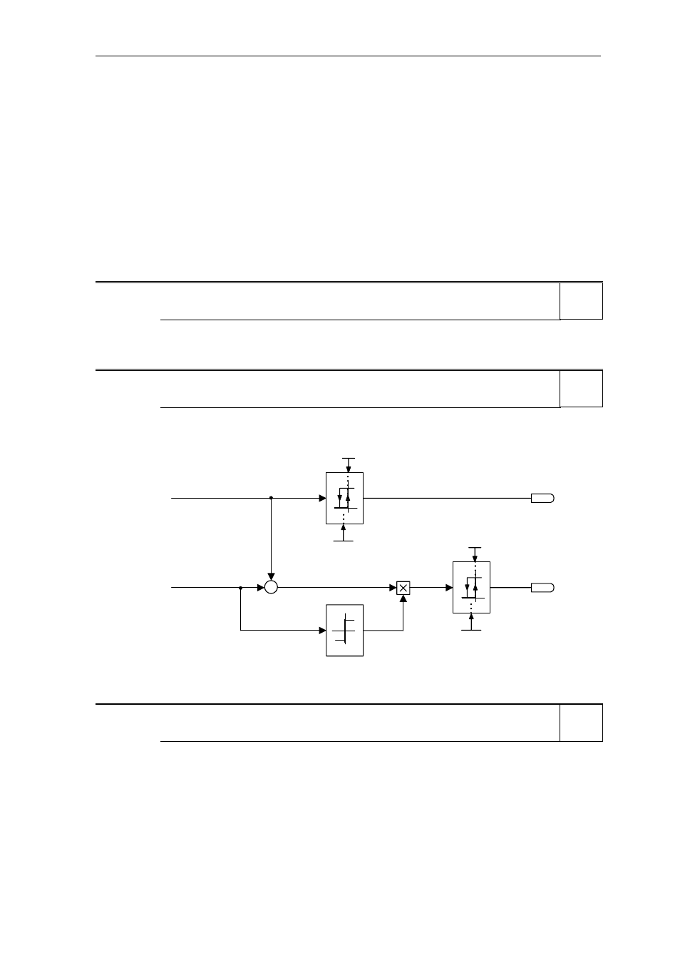
P2150[3]
Hysteresis frequency f_hys
Min: 0.00
CStat:
CUT
Datatype: Float Unit:
Hz
Def:
3.00
P-Group: ALARMS
Active: Immediately
QuickComm.: No
Max: 10.00
Defines hysteresis level applied for comparing frequency and speed to threshold as illustrated in the
diagram below.
-1
1
0
0
1
{
-
0
1
{
0
Hyst. freq. f_hys
0.00 ... 10.00 [Hz]
P2150.D (3.00)
Hyst . freq. f_hys
0.00 ... 10.00 [Hz]
P2150.D (3.00)
f_act > 0
| f_act | >= | f_set |
f_act > 0
| f_act| >= | f_set |
f_act
f_set
r2197 Bit03
r0052 Bit14
r2197 Bit04
r0053 Bit06
Index:
P2150[0] : 1st. Drive data set (DDS)
P2150[1] : 2nd. Drive data set (DDS)
P2150[2] : 3rd. Drive data set (DDS)
P2153[3]
Time-constant frequency filter
Min: 0
CStat:
CUT
Datatype: U16 Unit:
ms
Def:
5
P-Group: ALARMS
Active: Immediately
QuickComm.: No
Max: 1000
Specifies time constant of first-order frequency filter. The filtered frequency is then compared to the
thresholds.
Index:
P2153[0] : 1st. Drive data set (DDS)
P2153[1] : 2nd. Drive data set (DDS)
P2153[2] : 3rd. Drive data set (DDS)
Details:
See diagram in P2155, P2157 and P2159
Level
4
Level
3
Level
2