Displaying and maintaining p2mp gre tunnels, Basic p2mp gre tunnel configuration example, Network requirements – H3C Technologies H3C SecPath F1000-E User Manual
Page 63
51
Displaying and maintaining P2MP GRE tunnels
Task Command
Remarks
Display the tunnel entry
information of a P2MP GRE tunnel
interface.
display gre p2mp tunnel-table interface
tunnel number [ | { begin | exclude |
include } regular-expression ]
Available in any view
Clear the tunnel entry information
of a P2MP GRE tunnel interface.
reset gre p2mp tunnel-table [ interface tunnel
number [ dest-address tunnel-dest-address] ] Available in user view
Basic P2MP GRE tunnel configuration example
NOTE:
In this configuration example, either Router A or Router B is the SecPath firewall.
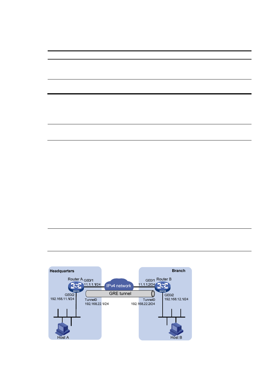
Network requirements
A company has a network at the headquarters and each of its branches. Implement communication
between the headquarters and the branches through GRE, but forbid communication between the
branches.
shows a simplified scenario, where there is only one branch.
•
Router A is the gateway at the headquarters, and Router B is the gateway of the branch.
•
Host A is an internal user at the headquarters and Host B is an internal user at the branch. A GRE
tunnel is established between Router A and Router B to implement intercommunication between
Host A and Host B.
If you use P2P GRE tunnels, the number of GRE tunnels to be configured is the same as that of the
branches. To simplify the configuration at the headquarters, you can create a P2MP GRE tunnel interface
on Router A, and configure a GRE over IPv4 tunnel interface on Router B.
NOTE:
This example gives only the configuration on one branch gateway (Router B). The configuration on other
branch gateways is similar.
Figure 53 Network diagram
- H3C SecPath F5000-A5 Firewall H3C SecPath F1000-A-EI H3C SecPath F1000-E-SI H3C SecPath F1000-S-AI H3C SecPath F5000-S Firewall H3C SecPath F5000-C Firewall H3C SecPath F100-C-SI H3C SecPath F1000-C-SI H3C SecPath F100-A-SI H3C SecBlade FW Cards H3C SecBlade FW Enhanced Cards H3C SecPath U200-A U200-M U200-S H3C SecPath U200-CA U200-CM U200-CS