Ipsec stateful failover, Figure 98 – H3C Technologies H3C SecPath F1000-E User Manual
Page 168
156
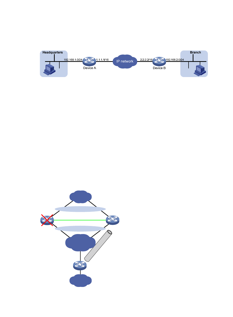
static route to branch network 192.168.2.0/24 for the IPsec protected traffic from the headquarters to the
branch. The result is the same as configuring a static route with the destination address 192.168.2.0/24
and the next hop 2.2.2.2.
Figure 98 An IPsec VPN
You can advertise the static routes created by IPsec RRI in the internal network. IPsec RRI can quickly
create new routes for forwarding IPsec VPN traffic when an active link fails in a load balanced or stateful
failover environment, or when IPsec VPN traffic cannot reach the peer gateway through the default local
gateway.
IPsec stateful failover
The IPsec stateful failover function enables hot backup of IPsec service data between two devices and is
usually deployed on two devices at the headquarters to improve the availability of IPsec service.
The IPsec stateful failover function is based on the Virtual Router Redundancy Protocol (VRRP). The two
devices configured for this function join the same VRRP group and act as a single virtual device. They use
the virtual IP address of the virtual device to communicate with remote devices.
The IPsec stateful failover function can work only in standard VRRP mode. In this mode, only one device
(the master) processes and forwards IPsec traffic; the other device (the backup) only receives IPsec service
data synchronized from the master. When the master fails, the backup immediately takes over to forward
IPsec traffic. This switchover process is transparent to remote devices. No extra configuration is required
on remote devices and no IPsec re-negotiation is required after the switchover.
Figure 99 IPsec stateful failover
LAN
Device A
Device B
Device C
Failover link
Master
Backup
Virtual router 1
Virtual router 2
IP
se
c
tu
nn
el
LAN
Internet
- H3C SecPath F5000-A5 Firewall H3C SecPath F1000-A-EI H3C SecPath F1000-E-SI H3C SecPath F1000-S-AI H3C SecPath F5000-S Firewall H3C SecPath F5000-C Firewall H3C SecPath F100-C-SI H3C SecPath F1000-C-SI H3C SecPath F100-A-SI H3C SecBlade FW Cards H3C SecBlade FW Enhanced Cards H3C SecPath U200-A U200-M U200-S H3C SecPath U200-CA U200-CM U200-CS