Configuring device b – H3C Technologies H3C SecPath F1000-E User Manual
Page 20
8
•
Click Apply.
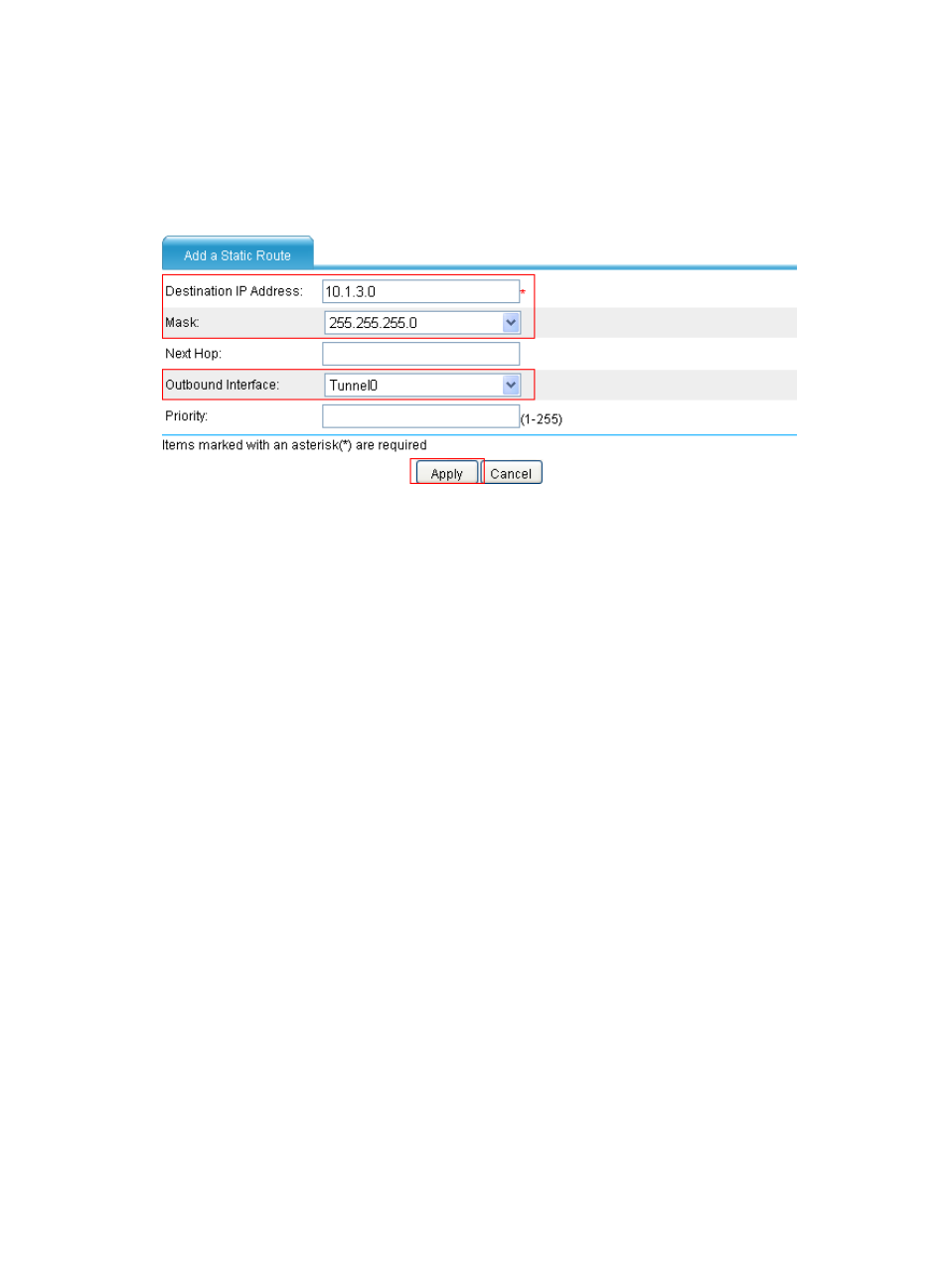
# Configure a static route from Device A through interface Tunnel 0 to Group 2.
•
Select Network > Routing Management > Static Routing from the navigation tree and then click
Add to perform the configurations shown in
Figure 12 Adding a static route from Device A through interface Tunnel 0 to Group 2
•
Enter 10.1.3.0 as the destination IP address.
•
Select mask 255.255.255.0.
•
Select Tunnel0 as the outbound interface.
•
Click Apply.
Configuring Device B
The configuration pages of Device B are similar to those of Device A. See the figures provided for
configurations on Device A.
# Configure an IPv4 address and assign the interfaces to security zones. (Details not shown.)
# Create a GRE tunnel interface.
•
Select VPN > GRE > GRE from the navigation tree and then click Add.
•
Enter 0 in the Tunnel Interface field.
•
Enter IP address/mask 10.1.2.2/24.
•
Select Trust from the Zone list. (Select a security zone according to your network configuration.)
•
Enter the source end IP address 2.2.2.2, the IP address of GigabitEthernet 0/1.
•
Enter the destination end IP address 1.1.1.1, the IP address of GigabitEthernet 0/1 on Device A.
•
Click Apply.
# Configure a static route from Device B through interface Tunnel 0 to Group 1.
•
Select Network > Routing Management > Static Routing from the navigation tree and then click
Add.
•
Enter 10.1.1.0 as the destination IP address.
•
Select mask 255.255.255.0.
•
Select Tunnel0 as the outbound interface.
•
Click Apply.
- H3C SecPath F5000-A5 Firewall H3C SecPath F1000-A-EI H3C SecPath F1000-E-SI H3C SecPath F1000-S-AI H3C SecPath F5000-S Firewall H3C SecPath F5000-C Firewall H3C SecPath F100-C-SI H3C SecPath F1000-C-SI H3C SecPath F100-A-SI H3C SecBlade FW Cards H3C SecBlade FW Enhanced Cards H3C SecPath U200-A U200-M U200-S H3C SecPath U200-CA U200-CM U200-CS