Ground fault setting range, Ground fault trip, Ground fault setting range ground fault trip – Rockwell Automation 193-EC1_2_3_5, 193-ECPM,592-EC1_2_3_5 E3 and E3 Plus Solid-State Overload Relay User Manual User Manual
Page 53
Rockwell Automation Publication 193-UM002I-EN-P - December 2011
53
Protective Trip & Warning Functions Chapter 3
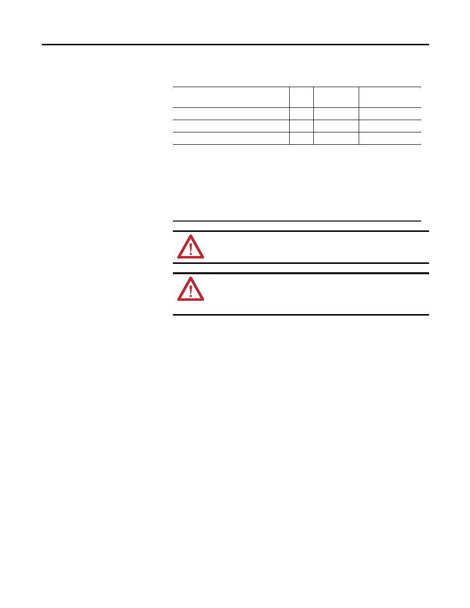
Figure 32 - Ground Fault Capabilities
Ground Fault Setting Range
Series A and B E3 Plus Overload Relays have one ground fault sensing range, 1…5
A. E3 Plus Overload Relays, 193/592-EC3_ _ and 193/592-EC5_ _ Series C and
later, using an193-CBCT external core balance ground fault sensor have four
sensing ranges which are selectable via the GF Sensing Range, Parameter 106.
These ranges are:
• 20…100 mA — For resistive loads only. For motor load information,
consult your local Rockwell Automation sales office or Allen-Bradley
distributor.
• 100…500 mA
• 200 mA …1.0 A
• 1.0…5.0 A
Ground Fault Trip
The E3 Plus Overload Relay will trip with a ground fault indication if:
• no trip currently exists,
• ground fault protection is enabled,
Catalog Number
Series
Ground Fault
Method
Ground Fault
Trip/Warning Range
193/592-EC2_ _, & 193-EC2ZZ (
≤
90A)
B & C
Internal 1…5 A 1…5 A
193-EC2_ _, except for 193-EC2ZZ (> 90A)
B
External
➊
1…5 A
193/592-EC3_ _, & 193-EC5_ _
C
External
➋➌
20mA…5 A
➊
A Catalog Number 825-CBCT Core Balance Ground Fault Sensor must be used.
➋
One of the following Catalog Number 193-CBCT_ Core Balance Ground Fault Sensors must be
used:
1 — Ø 20 mm window
2 — Ø 40 mm window
3 — Ø 65 mm window
4 — Ø 85 mm window
➌
20…100 mA for resistive loads only. For motor load information, consult your local Rockwell
Automation sales office or Allen Bradley distributor.
ATTENTION: The E3 Plus Overload Relay is not a ground fault circuit
interrupt or for personal protection as defined in Article 100 of the NEC.
ATTENTION: The E3 Plus Overload Relay is not intended to signal a
disconnecting means to open the faulted current. A disconnecting device
must be capable of interrupting the maximum available fault current of
the system on which it is used.