Rockwell Automation 193-EC1_2_3_5, 193-ECPM,592-EC1_2_3_5 E3 and E3 Plus Solid-State Overload Relay User Manual User Manual
Page 102
102
Rockwell Automation Publication 193-UM002I-EN-P - December 2011
Chapter 4 DeviceNet™ Node Commissioning
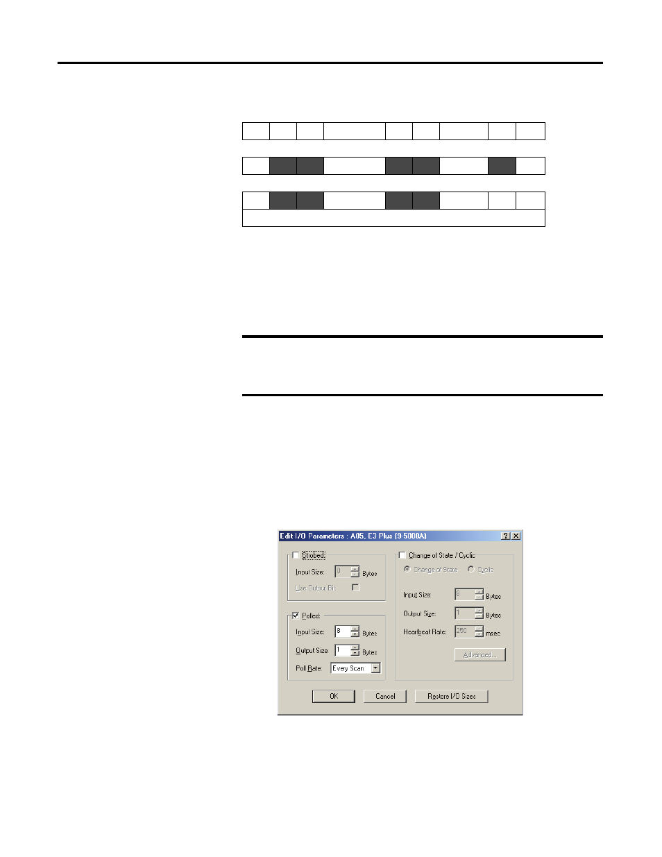
Table 26 - Default Output Assemblies
Choosing the size and format of the I/O data that is exchanged by the E3
Overload Relay is done by selecting Input and Output Assembly instance
numbers. Each assembly has a given size (in bytes). This instance number is
written to the Input Assembly and Output Assembly parameters. The different
instances/formats allow for user programming flexibility and network
optimization.
Mapping the Scanner to the Scan List
The Automap feature available in all Rockwell Automation scanners
automatically maps the information. If the default I/O assemblies are not used,
the values must be changed in the scan list.
1.
Select Edit I/O Parameters from the Scan List tab of the scanner. The
following window appears.
2.
Change the default I/O assemblies in the Polled section of the window,
then select OK.
Byte Bit 7 Bit 6 Bit 5
Bit 4 Bit 3 Bit 2
Bit 1 Bit 0
Instance 103 E3
0
Remote Trip
➊
Fault Reset
Out A
Instance 103 E3 Plus
0
Remote Trip
➊
Fault Reset Out B Out A
➊
Series C and later.
IMPORTANT The Output Assembly and Input Assembly parameter values cannot be
changed while the E3 Overload Relay is online with a scanner. Any
attempts to change the value of this parameter while online with a
scanner will result in the error message “Object State Conflict”.