Output setup group – Rockwell Automation 193-EC1_2_3_5, 193-ECPM,592-EC1_2_3_5 E3 and E3 Plus Solid-State Overload Relay User Manual User Manual
Page 127
Rockwell Automation Publication 193-UM002I-EN-P - December 2011
127
Programmable Parameters Chapter 5
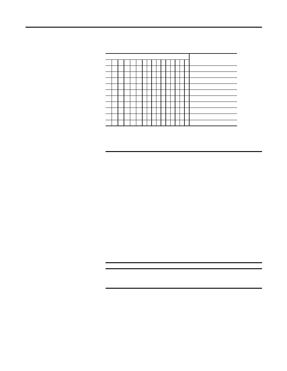
Table 63 - Change of State Mask Bit Function Detail
Output Setup Group
E3 is Normal – No Trip Present
In normal operation, the E3 Overload Relay firmware latches Out A and Out B
commands received through Polled I/O and Explicit messaging. The latched
states are applied to the outputs until the next command is received.
Bit
Function
15 14 13 12 11 10 9 8 7 6 5 4 3 2 1 0
X Trip
X
Warning
X
Output A
X
Output B (E3 Plus)
X
Input #1
X
Input #2
X
Input #3 (E3 Plus)
X
Input #4 (E3 Plus)
X
Motor Current
X
Ground Fault Current (E3 Plus)
IMPORTANT The parameters in the Output Setup Group provide great flexibility in
terms of output relay(s) operation under the conditions of Protection
Faults, Comm Fault, and Comm Idle. It is important, therefore, that the
installer fully understands the use of these parameters, their interaction
with Trip Enable, Parameter 24, and the order of priority.
Order of Priority
The Out_Pr FltState parameter settings take priority over the other
settings.
If Comm Fault and Comm Idle are enabled (set to 1) in Trip Enable, the
state that the output(s) assumes is first determined by the settings in the
Out_Pr FltState and Out_PrFltValue parameters.
If Out_Pr FltState is set to 1 = ignore fault, the state of the output(s) will
be determined by the Out_DN FltState and Out_DN FltValue, and
Out_DN IdlState and Out_DN IdlValue settings.
If Comm Fault and Comm Idle are disabled (set to 0) in Trip Enable, the
state that the output(s) assumes will be determined by the Out_DN
FltState and Out_DN Flt Value, and Out_DN IdlState and Out_DN
IdleValue settings.
IMPORTANT The following information addresses the behavior variation between
Series A and Series B and later products in relation to the Output Setup
parameters.