Rockwell Automation 193-EC1_2_3_5, 193-ECPM,592-EC1_2_3_5 E3 and E3 Plus Solid-State Overload Relay User Manual User Manual
Page 152
152
Rockwell Automation Publication 193-UM002I-EN-P - December 2011
Chapter 7 Voltage Parameters
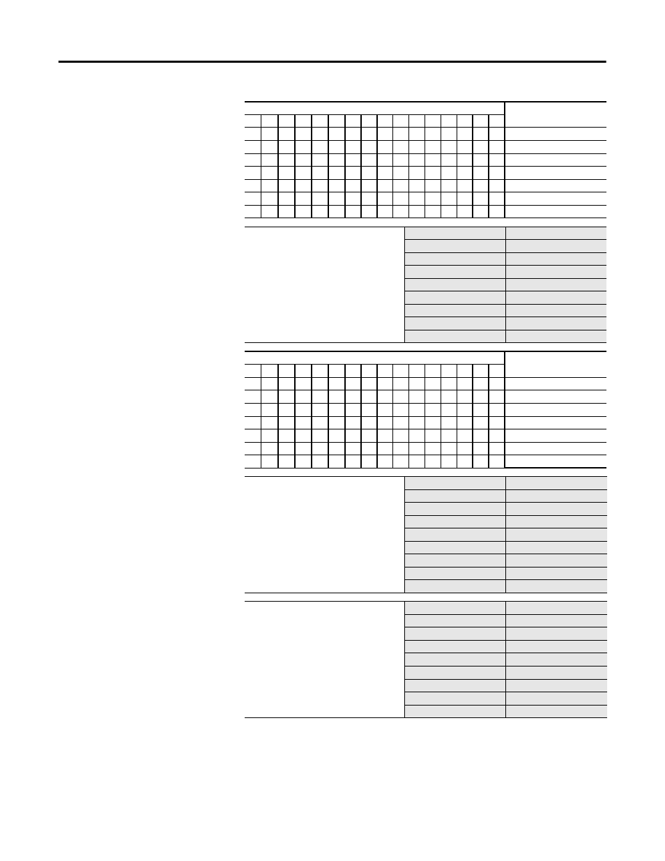
Bit
Function:
15 14 13 12 11 10 9
8
7
6
5
4
3
2
1
0
X
Voltage Hardware Fault
X
Under Volt L-L
X
Over Volt L-L
X
Voltage Unbalance
X
Phase Rotation
X
Under Frequency
X
Over Frequency
V Warn Enable
This parameter allows the installer to
enable or disable voltage based warning
functions separately.
1 = Warning
0 = No Warning
Parameter Number
159
Access Rule
Get/Set
Data Type
UINT
Object Mapping
0Fhex-9F-01
Group
Voltage Setup
Units
—
Minimum Value
0000000000000000
Maximum Value
0000000000111111
Default Value
0000000000000001
Bit
Function:
15 14 13 12 11 10 9
8
7
6
5
4
3
2
1
0
X
Voltage Hardware Fault
X
Under Volt L-L
X
Over Volt L-L
X
Voltage Unbalance
X
Phase Rotation
X
Under Frequency
X
Over Frequency
UV Inhibit Time
This parameter defines the amount of time
for which an under voltage detection is
inhibited during a motor starting
sequence.
Parameter Number
215
Access Rule
Get/Set
Data Type
USINT
Object Mapping
0Fhex-D7-01
Group
Voltage Setup
Units
Seconds
Minimum Value
0
Maximum Value
250
Default Value
10
UV Trip Delay
This parameter allows the installer to
program a time duration for which an
under voltage condition must exist prior to
the device tripping.
Parameter Number
216
Access Rule
Get/Set
Data Type
USINT
Object Mapping
0Fhex-D8-01
Group
Voltage Setup
Units
Seconds
Minimum Value
0.1
Maximum Value
25.0
Default Value
1.0