3 installation procedure, Expansion unit spacer, Visual kv series – KEYENCE Visual KV Series User Manual
Page 90
Chapter 2 System Installation
1-66
2
Visual KV
Series
2.1.3
Installation Procedure
This section describes how to attach a connected unit directly to a panel, to a DIN
rail, or to a DIN rail with an expansion unit spacer.
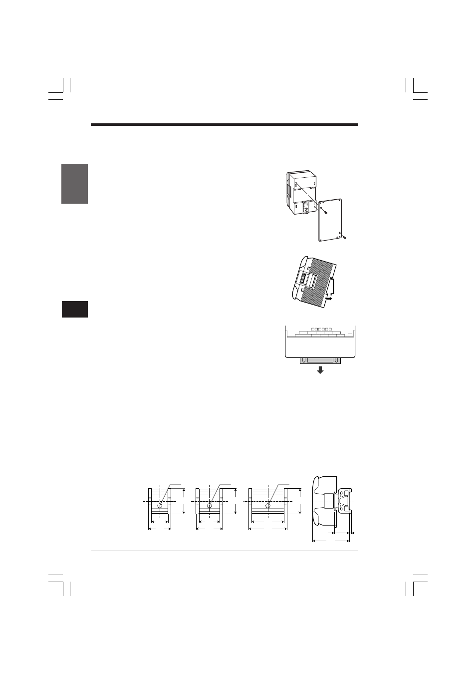
■ Attaching a unit directly to a panel
Attach the metal fixture for screw tightening to each
KV Series unit using the countersunk-head screws
through the countersunk holes. Mount the fixture
directly to the panel.
■ Attaching a unit to a DIN rail
Hang an upper claw of a Visual KV Series basic unit
to the upper side of the DIN rail, and press the basic
unit onto the DIN rain until a click sound is heard.
■ Removing a unit from a DIN rail
Pull a lower claw of a Visual KV Series basic unit
downward from the front direction using a screw-
driver, and then remove the basic unit from the DIN
rail.
Expansion unit spacer
When an expansion unit spacer is attached to a Visual KV Series expansion unit, its
height becomes flush with an AC power type Visual KV Series basic unit.
The procedure to attach a Visual KV Series expansion unit to an expansion unit
spacer is the same as the procedure to attach a Visual KV Series unit to a DIN rail.
Refer to the instruction manual supplied with the Visual KV Series for DIN rail
mounting.
■ Dimensions for expansion unit spacers
2.1 Installation Environment
42.8
38
28
ш4.0
42.8
45
35
ш4.0
42.8
65
66
25.3
4
55
ш4.0
OP-35342
Spacer for 4-I/O
expansion unit
OP-35343
Spacer for 8-I/O
expansion unit
OP-35344
Spacer for 16-I/O
expansion unit
KVHKA Chap 02.p65
08.3.11, 11:11 AM
66