4 wiring: kv-c16x/c32x connector input module, Parts and functions, Kv -300 – KEYENCE Visual KV Series User Manual
Page 195
5.2 Module/Unit Specifications
KV
-300
KV-10/80
1
5
Chapter 5 KV-300 Hardware
1-171
5.2.4
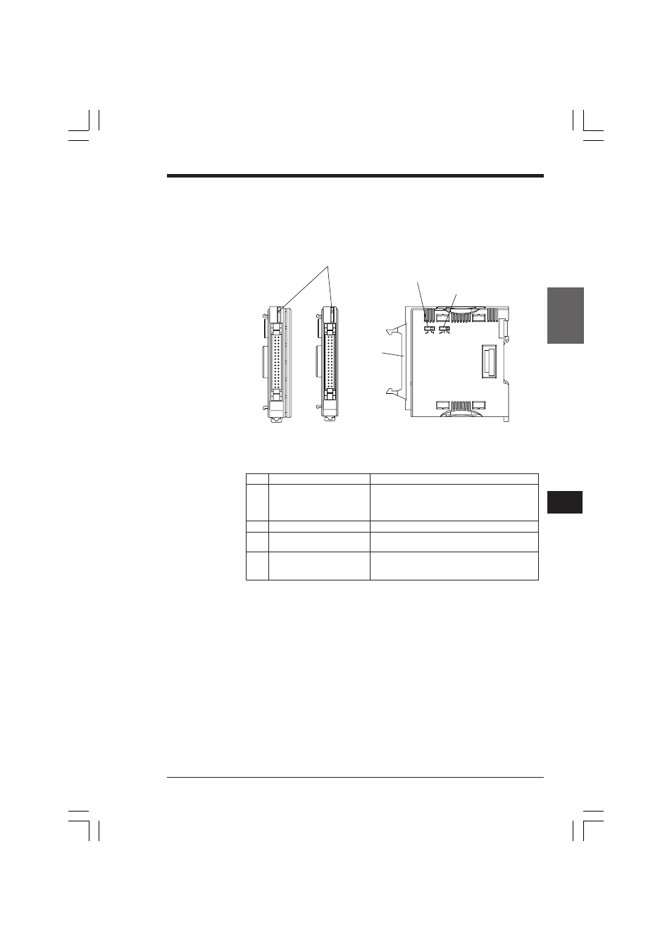
Wiring: KV-C16X/C32X Connector Input Module
Parts and functions
1. READY/SELECT indicator (green)
24V
5V
1ms
0ms
10ms
2. 34-pin input
connector
3. Input voltage selection switch
4. Input time constant
selection switch
KV-C32X
KV-C16X
Includes OP-23139 34-pin connector.
No.
Name
Function
1
READY/SELECT indicator
Green LED flashes when the module is selected to
(green)
be displayed in CPU I/O indicators, lights when not
selected (during normal operation), and goes out
when an error occurs.
2
Input connector
32 input port connector (34-pin)
3
Input voltage selection
For selecting input voltage of 24 V or 5 V
switch
4
Input time constant selection
For selecting input time constant
switch
(Choose between 25 µs ±20%,1 ms ±20%,
or 10 ms ±20%)
KVHKA Chap 05.p65
08.3.11, 11:14 AM
171
- LR-TB2000 Series (12 pages)
- LR-TB5000 Series (12 pages)
- LR-ZB250AN/AP (4 pages)
- LR-ZB250AN/P (3 pages)
- LR-ZBxN/P Series (3 pages)
- LR-ZBxxB (3 pages)
- OP-85135 (1 page)
- PZ-G Series (2 pages)
- PZ-V/M (2 pages)
- PS-N10 Series (12 pages)
- PX-10 (10 pages)
- CZ-V21A(P) (10 pages)
- CZ-K1(P) (8 pages)
- CZ-V1 (8 pages)
- FS-N10 Series (6 pages)
- FS-N10 Series (116 pages)
- FS-N15CN (1 page)
- FU-93(Z) (2 pages)
- FU-V Series (2 pages)
- FS-V30 (6 pages)
- FU-A40 (1 page)
- NU/FS-N Series (16 pages)
- FS-V33(P) (8 pages)
- FS-V21 (4 pages)
- FS-V22 (4 pages)
- FS-V11(P) (4 pages)
- FS-V1(P) (4 pages)
- LV-N10 Series (12 pages)
- LV-N10 Series (112 pages)
- LV-S62 (1 page)
- OP-84350 (1 page)
- LV-SA (10 pages)
- LV-SB (12 pages)
- OP-87305 (1 page)
- LV Series (10 pages)
- LV-B102 (1 page)
- EV-108M(U) (1 page)
- EZ Series (1 page)
- EM Series (1 page)
- ES-M1(P) (3 pages)
- EX-V Series (120 pages)
- EX-500(W) Series (16 pages)
- GV Series (10 pages)
- IA Series (8 pages)
- LB-1000(W) (24 pages)