Communications control procedure, Kv -300 – KEYENCE Visual KV Series User Manual
Page 295
7.6 Display Interface Mode Programming
KV-300 Series Only
KV
-300
KV-10/80
Chapter 7 KV-L2 Serial Interface Module
1-271
1
7
Note 1: Turn off the power switches before setting switches.
Note 2: Communications protocols for the modules to be connected must be identi-
cal; otherwise, communication will fail. For settings of external units to be connected,
refer to the operation manuals supplied with the respective units.
Note 3: For settings of the display device, refer to the User’s Manual of your display
device.
Note 4: The communications protocols settings apply to both ports 1 and 2. The two
ports cannot be set to different protocols.
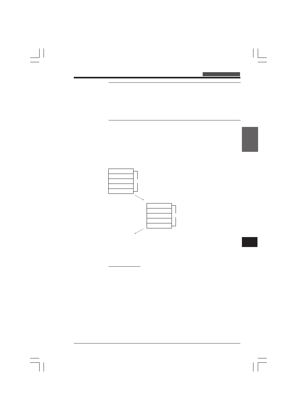
Communications control procedure
In Display Interface mode, the KV-L2 provides a special interactive communications
procedure, detailed below.
Communications procedure
In Display Interface mode, the host computer sends a command to the KV-L2 and
the KV-L2 automatically returns a response.
FCS (frame check sequence)
The FCS is a method of detecting communications errors. An 8-bit exclusive OR
from the top of the command or response up to the last character of the text is
converted into a 2-character ASCII code.
Calculation example
@ 0
1
W D
0
3
E
8
1
9
6
4
2
6
*
CR
station no. header code---------------------------text---------------------------FCS terminator
@ 0
1
0
0
0
0
0
0
Exclusive OR
0
0
0
1
1
0
0
0
0
Exclusive OR
1
0
0
1
1
0
0
0
1
Exclusive OR
1
0
0
1
1
0
0
0
1
:
:
:
:
6
0
0
1
1
0
1
1
0
Exclusive OR
4
0
0
1
1
0
1
0
0
Exclusive OR
---------------------------------------------------------
0
0
1
0
0
1
1
0
ASCII
2
6
<----------FCS Value
(Host computer)
Station no.
Header code
Text
FCS
Terminator
Command
KV-L2
Station no.
Header code
Text
FCS
Terminator
Response
KVHKA Chap 07_5to10.p65
08.3.11, 11:18 AM
271