KEYENCE FS-10 User Manual
Instruction manual, Hybrid fiberoptic sensors, Safety precautions
1
WARNING
Accessories
• Instruction manual (x 1)
• Mounting bracket [FS-V11(P) only]
• End unit (x 2) [FS-V12(P) only]
• Directions (x 1) [FS-V12(P) only]
SAFETY PRECAUTIONS
• This product is just intended to detect the object(s). Do not use
this product for the purpose to protect a human body or a part
of human body.
• This product is not intended for use as explosion-proof
product. Do not use this product in a hazardous location and/or
potentially explosive atmosphere.
SPECIFICATIONS
1. The response time varies depending on the number of expansion units connected.
2. The orange LED is normally part of the bar graph LED monitor. It is used as a calibration
indicator during the setting of the sensitivity.
3. When several units are connected, the allowable ambient temperature changes depending
on the following conditions. To connect several units, be sure to mount them to a DIN rail
(metal DIN rail). Make sure that the output current is 20 mA. max.
• When 3 to 10 units are connected: -10 to +50 °C (14 to 122°F)
• When 11 to 16 units are connected: -10 to +45 °C (14 to 113°F)
Model
NPN output
FS-V11
FS-V12
FS-V10
PNP output
FS-V11P
FS-V12P
—
Light source
Red LED
Response time
250 µs (FINE)/500 µs (TURBO)/
410 µs to 1.7 ms
1.
1 ms (SUPER)
Operation mode
LIGHT-ON/DARK-ON (switch selectable)
Indicators
Output indicator: Red LED
Digital LED monitor: Red LED
Bar graph LED monitor: Green/Orange LED
2.
Calibration indicator: Orange LED
2.
Timer function
OFF-delay: 40 ms, 10 ms
Timer OFF
Control output
NPN or PNP open-collector 24V 100mA max.
Residual voltage: 1V max.
Protection circuit
Reverse polarity protection, Over-current protection,
Surge absorber
Power supply voltage
12 to 24 VDC ±10%, Ripple (P-P) 10% max, Class 2
Current consumption
50 mA max.
Ambient illumination
Candescent lamp: 10,000 lx max., Sunlight: 20,000 lx max
Ambient temperature
3.
-10 to +55°C (14 to 131°F), No freezing.
Relative humidity
35 to 85%, No condensation
Vibration
10 to 55 Hz, 1.5 mm double amplitude in X, Y and
Z directions for two hours
Shock immunity
500 m/s
2
in X, Y and Z directions, three times each
Housing material
Body/Cover: Polycarbonate
Weight
Approx. 80 g
Approx. 45 g
Approx. 20 g
(including 2-m cable)
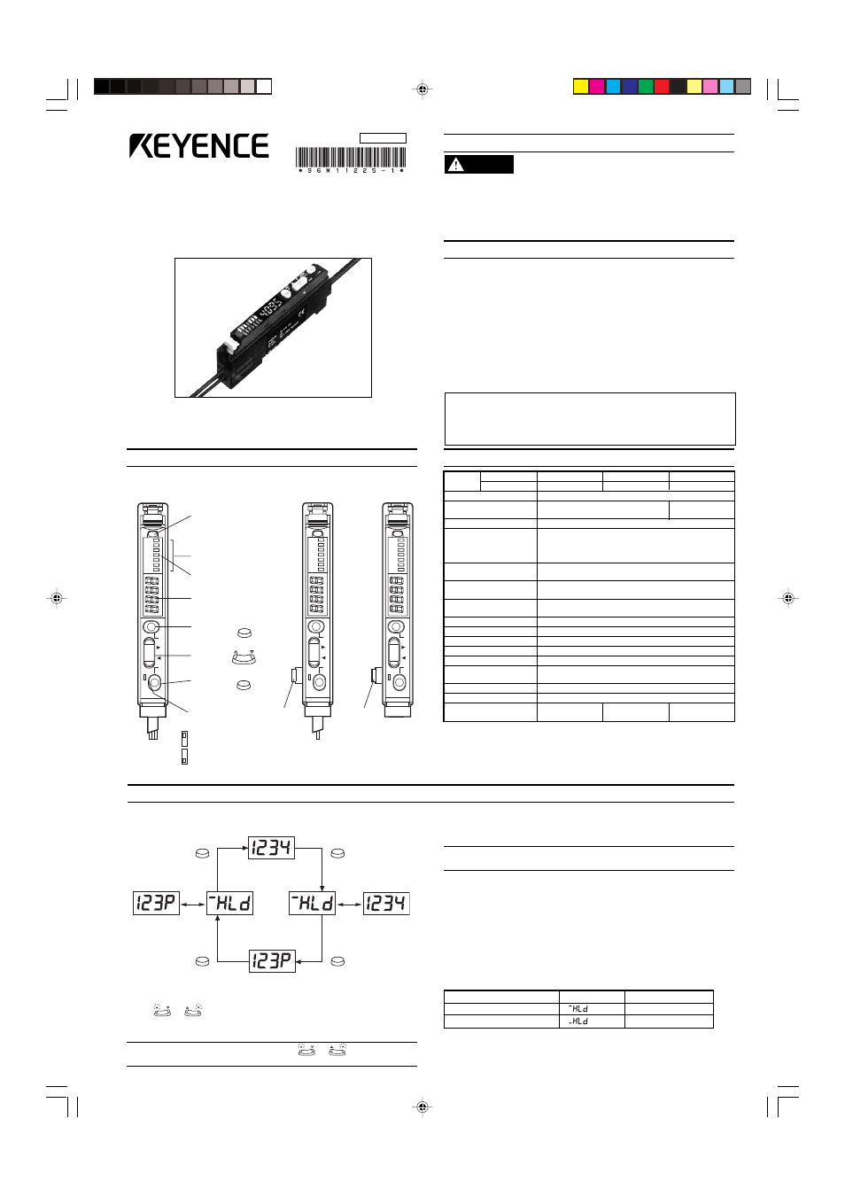
SELECTING DISPLAYED DATA
■ Displaying received light intensity
Received light intensity is displayed approximately 4000 is the
maximum setting.
Note: The MAX and MIN values vary depending on the fiber unit
connected.
■ Displaying excess gain
Received light intensity is converted by defining the setting value as
100 P (%).
■ Displaying the hold value
The peak value or the minimum value of the received light intensity or
excess gain is displayed.
The setting of the output selector switch determines whether the peak
value or the minimum value is displayed.
PART NAMES AND FUNCTIONS
FS-V11(P)
(Main unit)
SUPER
D. ON
MODE
SET
L. ON
TURBO
FINE
SET
40ms
OFF
10ms
SET
MODE
SUPER
D. ON
MODE
SET
L. ON
TURBO
FINE
SET
40ms
OFF
10ms
Operation indicator
(Red)
Bar graph LED
monitor
Calibration indicator
(Orange)
Digital LED monitor
Auto SET
button
Manual
button
MODE
button
Output
selector switch
DARK-ON
LIGHT-ON
3-core
cable
FS-V12(P)
(Expansion unit)
Expansion
connector
Single-core
cable
Output selector switch
Display
Hold value
LIGHT-ON
Peak-hold value
DARK-ON
Bottom-hold value
Displaying the setting value
Press
or
once while the received light intensity is displayed.
The setting value flashes for 2 seconds, and then the received light
intensity appears once more.
Note: To change the setting value, press
or
while the setting
value is flashing.
MODE
MODE
MODE
MODE
Press this
button once.
Received light intensity
Hold display
(Light intensity)
Press this
button once.
Display
changes
alternately.
Display
changes
alternately.
Press this
button once.
Press this
button once.
Hold display
(Excess gain)
The display changes every time the MODE button is pressed.
Excess gain display (%)
SUPER
D. ON
MODE
SET
L. ON
TURBO
FINE
SET
40ms
OFF
10ms
Expansion
connector
FS-V10
(Expansion unit)
PRECAUTIONS ON REGULATIONS AND STANDARDS
■ UL Certificate
This product is an UL/C-UL Listed product.
• UL File No. E301717
• Category
NRKH,NRKH7
• Enclosure
Type 1 (Based on UL50)
Be sure to consider the following specifications when using this
product as an UL/C-UL Listed Product.
• Use the power supply with Class 2 output defined in NFPA70 (NEC:
National Electrical Code).
• Power supply/ Control input/ Control output circuits shall be
connected to a single Class 2 source only.
• Use with the over current protection device which is rated 24V or
more and not more than 2A.
Hybrid Fiberoptic Sensors
FS-V11(P)/12(P)/10
Instruction Manual
96M11225
Read this manual before using the product in order to achieve
maximum performance.
Keep this manual in a safe place after reading it so that it can be used
at any time.
Document Outline
- SAFETY PRECAUTIONS
- PART NAMES AND FUNCTIONS
- SPECIFICATIONS
- SELECTING DISPLAYED DATA
- SETTING THE SENSITIVITY(AUTOMATIC CALIBRATION)
- CHANGING THE SETTING VALUE(MANUAL CALIBRATION)
- SELECTING MODE (POWER/TIMER)
- MUTUAL INTERFERENCE SUPPRESSION FUNCTION
- I/O CIRCUIT
- MOUNTING MAIN UNIT
- MOUNTING EXPANSION UNITS
- CONNECTING FIBER UNIT
- DIMENSIONS
- HINTS ON CORRECT USE
- WARRANTIES