KEYENCE CZ-V22A(P) User Manual
Cz-v21a(p)/v22a(p), Instruction manual, Rgb digital fiberoptic sensor
1
E CZ-V21A(P)/V22A(P)-IM
RGB Digital Fiberoptic Sensor
CZ-V21A(P)/V22A(P)
Instruction Manual
BE SURE TO READ THESE MESSAGES CAREFULLY
ACCESSORIES
■
Amplifier unit
• Mounting bracket: 1
• End unit: 2
• Instruction manual: 1
Supplied with the CZ-V21A(P) Supplied with the CZ-V22A(P)
■
Sensor head
Common:
• Mounting bracket: 1 (two types, one of each for the CZ-H72)
• Board nut: 1
CZ-H32/H35S/H37 only :
• M3 x 20 screw: 2
CZ-H52 only :
• M3 x 22 screw: 2
• Fiber insertion port cover seal: 1
• Ultraviolet ray spot check sheet : 1
CZ-H72 only :
• M3 x 30 screw: 2
• M3 x 6 screw: 2
PART NAMES
■
Amplifier unit
Display
* Film calibration indicator when using the CZ-H72
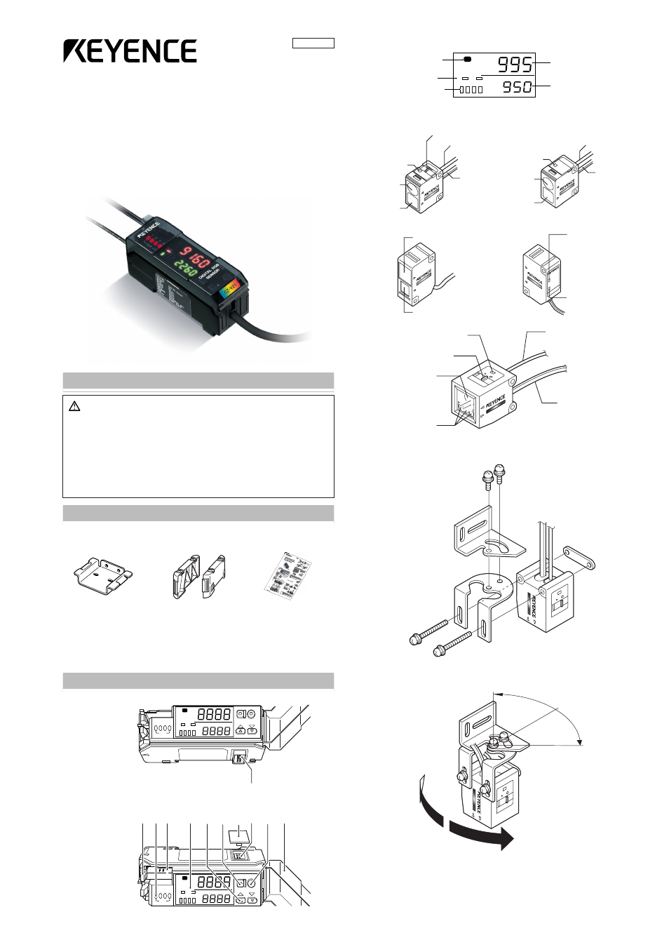
■
Sensor head
CZ-H32
CZ-H35S/H37S
CZ-H52
CZ-H72
■
Installing the supplied brackets on the CZ-H72
Install the two supplied brackets by combining them as shown below.
The sensor angle can be adjusted within 90° (± 45°).
(Refer to the lower right of page 9.)
Warning
• The CZ-V21(P)/V22(P) is just intended for the detection of target
objects. Do not use the CZ-V21(P)/V22(P) in a safety circuit to pro-
tect the human body.
• The CZ-V21(P)/V22(P) does not have an explosion-proof struc-
ture. Do not use it in a location where any flammable gases, liquid
or powder exist.
• The CZ-V21(P)/22(P) is a direct current type sensor. Application of
the AC power may lead to burst or fire.
• Do not directly look at the emitted LED beam.
• The CZ-H32/H35S/H37S/H72 are the Class 1 LED product in which
the light source LED is located in the amplifier unit.
• The CZ-H52 is the Class 1M LED product.
* When using the CZ-H52, be sure to read Precaution on Using CZ-
H52 on page 8.
A
B
MODE
BANK
1 2 3 4
SET
C
OUT
1 2 3 4
A
B
MODE
BANK
1 2 3 4
SET
C
OUT
1 2 3 4
Fixing le
v
e
r
Connection
protection co
v
e
r
MODE b
utton
Connection
connector
SET b
utton
Man
u
al adjustment
bu
tton
Output indicator
Displa
y
Dust co
v
e
r
Receiv
er connector
por
t
CZ-V22A(P)
CZ-V21A(P)
A
B
BANK
1 2 3 4
C
Color indicator*
(Lights at C/C+I mode)
Bank indicator
(At C/C+I mode)
Channel indicator
Current value monitor (red)
Setting value monitor (green)
CZ
-H
32
CZ-H35S
Detection
indicator
Emitter
Receiver
Spot selection switch
Light emission fiber
cable
Light reception
cable
Detection
indicator
Emitter
Receiver
Light emission
fiber cable
Light reception
cable
U
V
O
N
D
E
TE
C
T
C
Z-H
52
Receiver
Emitter
UV irradiation indicator
(green)
Detection indicator
(red)
Detection indicator
Spot selection switch
Emitter
Receiver
Light emission fiber cable
Light reception cable
96M1382