Outputting analog trimmer values, Kv -300 – KEYENCE Visual KV Series User Manual
Page 388
9.5 Programming Examples
KV-10/80 Series Only
KV
-300
KV-10/80
Chapter 9 KV-AD4/DA4 Analog I/O Unit
1-364
9
1. DM0996 is initialized when the power is turned ON.
(That is, #2000 is written to DM0996.)
2. ((trimmer 0 x 2000) ÷ 249) is calculated, and 0 to 2000 is written to DM0000.
3. (DM0000 + 2000) is calculated when input 0000 is ON, and the calculation result
is written to DM0001.
4. (2000 - DM0000) is calculated when input 0000 is OFF, and the calculation result
is written to DM0001.
5. Before the digital data is written to data memory for D/A conversion, check that
the data is #4095 or less.
Note: An unsteady value will be output if a value outside the range 0 to 4095 is
written to data memory for D/A conversion.
6. The output data will be updated at the rising edge of special utility relay 2800. (As
internal relay 1000 switches ON/OFF at each scan, the output data will be
updated every two scans.)
Outputting Analog Trimmer Values
This sample program outputs the value of analog trimmer 0 on the CPU.
Conditions
•
The value of trimmer 0 is converted to data for analog output.
•
The data is sent to analog output V0 on the KV-DA4.
(Digital data is written to data memory DM0996.)
•
When input 0000 is ON, 0 to +10 V is output. To increase the voltage, turn the
trimmer clockwise.
•
When input 0000 is OFF, -10 to 0 V is output. To decrease the voltage, turn the
trimmer counterclockwise.
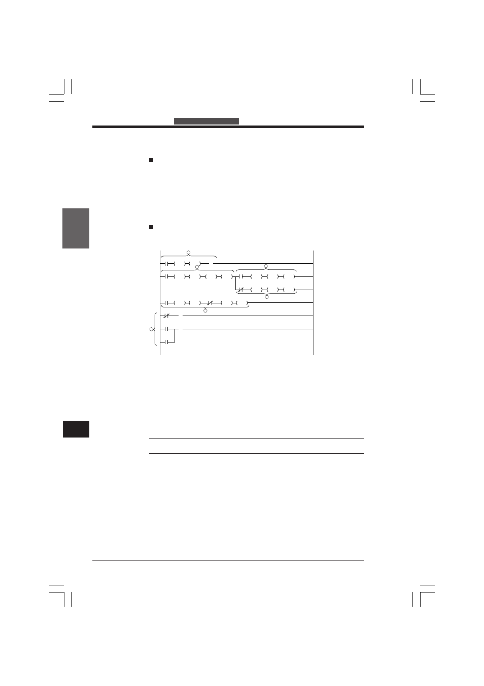
Ladder diagram
2002
DM0001
LDA
#04095
CMP
DM0001
STA
#02000
LDA
DM0000
SUB
DM0001
STA
DM0996
DIV
1000
1500
1000
1000
2800
2008 #02000
LDA
DM0996
STA
1500
0000
DM0000
LDA
#02000
ADD
DM0001
STA
2011
2007
0
TMIN
#02000
MUL
DM0000
STA
#00249
DIV
0000
1
2
3
4
5
6
( )
( )
( )
KVHKA Chap 09.p65
08.3.11, 11:20 AM
364