Kv-c16x/c32x, Kv -300 – KEYENCE Visual KV Series User Manual
Page 208
5.3 Module/Unit Connections
KV
-300
KV-10/80
5
Chapter 5 KV-300 Hardware
1-184
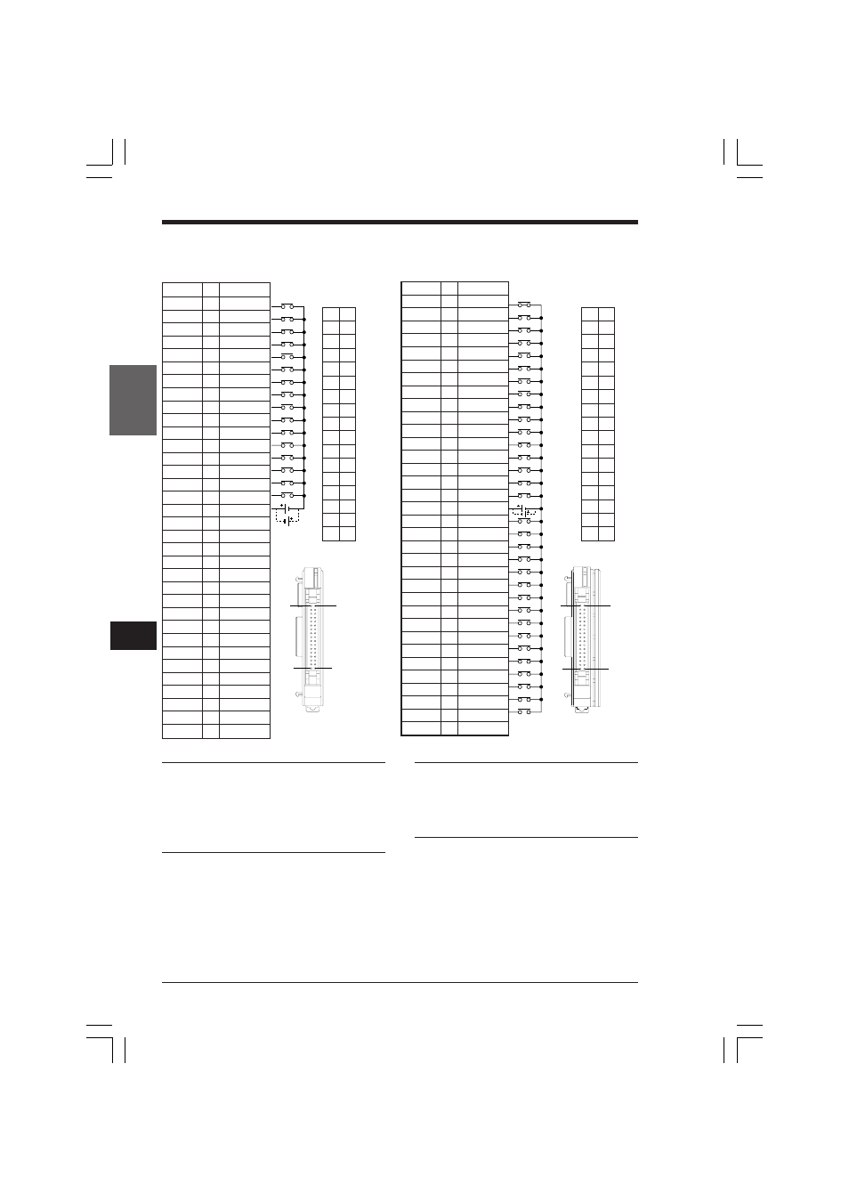
KV-C16X/C32X
Note 1: Pin nos. 18 to 34 are NC contacts that
are short-circuited internally. These can be used
as relay terminals.
Note 2: The number of input terminals that can
turn ON or remain ON simultaneously must not
exceed 8 (50%); otherwise, the module may be
damaged.
Connector Pin
assignment
1
18
2
19
3
20
4
21
5
22
6
23
7
24
8
25
9
26
10 27
11 28
12 29
13 30
14 31
15 32
16 33
17 34
1
18
17
34
Pin No. I/O Signal
1
I
000
2
I
001
3
I
002
4
I
003
5
I
004
6
I
005
7
I
006
8
I
007
9
I
008
10
I
009
11
I
010
12
I
011
13
I
012
14
I
013
15
I
014
16
I
015
17
I
Input COM
18
NC
19
NC
20
NC
21
NC
22
NC
23
NC
24
NC
25
NC
26
NC
27
NC
28
NC
29
NC
30
NC
31
NC
32
NC
33
NC
34
NC
Pin No. I/O Signal
1
I
000
2
I
001
3
I
002
4
I
003
5
I
004
6
I
005
7
I
006
8
I
007
9
I
008
10
I
009
11
I
010
12
I
011
13
I
012
14
I
013
15
I
014
16
I
015
17
I
Input COM
18
100
19
101
20
102
21
103
22
104
23
105
24
106
25
107
26
108
27
109
28
110
29
111
30
112
31
113
32
114
33
115
34
NC
24 VDC
24 VDC
Connector Pin
assignment
1
18
2
19
3
20
4
21
5
22
6
23
7
24
8
25
9
26
10 27
11 28
12 29
13 30
14 31
15 32
16 33
17 34
1
18
17
34
Note: The limit to simultaneous/continuous ON
terminals is shown in the graph in Appendix A.2,
P.1-384, comparing ambient temperature and
simultaneous/continuous ON terminals. The
module may be damaged if the ON rate exceeds
the recommendations shown in the graph.
➮ For instructions on crimping connectors to cables,
refer to page 1-189.
KVHKA Chap 05.p65
08.3.11, 11:14 AM
184