Kv -300 – KEYENCE Visual KV Series User Manual
Page 217
5.3 Module/Unit Connections
KV
-300
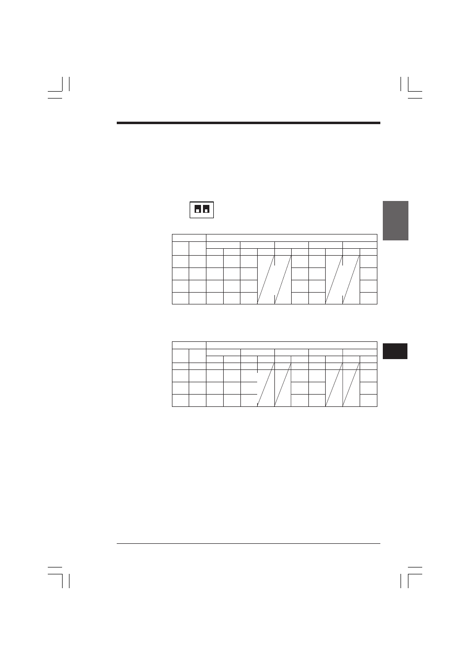
KV-10/80
1
5
Chapter 5 KV-300 Hardware
1-193
Switch
Expansion unit I/O relay No.
1
2
KV-8ER(W)/T(2W)
KV-8EX(W)
KV-8EYR(W)/T(2W)
KV-16EX(W)
KV-16EYR(W)/T(2W)
Input
Output Input
Output Input
Output Input
Output
Input
Output
OFF
OFF
–
–
–
–
–
–
ON
OFF
300
700
300
700
300
700
to 303
to 703
to 307
to 707
to 315
to 715
OFF
ON
400
800
400
800
400
800
to 403
to 803
to 407
to 807
to 415
to 815
ON
ON
–
900
–
900
–
900
to 903
to 907
to 915
1
2
ON
OFF
Switch
Expansion unit I/O relay No.
1
2
KV-8ER(W)/T(2W)
KV-8EX(W)
KV-8EYR(W)/T(2W)
KV-16EX(W)
KV-16EYR(W)/T(2W)
Input
Output Input
Output Input
Output Input
Output
Input
Output
OFF
OFF
100
600
100
600
100
600
to 103
to 603
to 107
to 607
to 115
to 615
ON
OFF
200
700
200
700
200
700
to 203
to 703
to 207
to 707
to 215
to 715
OFF
ON
300
800
300
800
300
800
to 303
to 803
to 307
to 807
to 315
to 815
ON
ON
400
900
400
900
400
900
to 403
to 903
to 407
to 907
to 415
to 915
Assignment of I/O relay numbers to expansion units
•
To assign I/O relay numbers to expansion units, use the channel setting switches
on each unit.
•
When changing the channel settings, be sure to turn the power OFF.
•
The channel setting switches for each expansion unit must have different set-
tings. (This also applies to input or output only expansion units.)
•
After setting the channel setting switches, write the numbers on the attached
channel number label, and apply it on each expansion unit.
Channel setting switch
■ Connection to KV-40, KV-24, KV-16 or KV-10
•
Do not set switches 1 and 2 to OFF on the KV-40. (Input relays 100 to 115 and
output relay 600 to 615 cannot be assigned to the KV-40.)
■ Connection to KV-80
•
Do not set switches 1 and 2 to OFF on the KV-80. (A maximum of 2 input only
expansion units can be connected. When three input units are connected, input
relays of the unit with switches 1 and 2 ON cannot be used.)
KVHKA Chap 05.p65
08.3.11, 11:14 AM
193