3 assembling the system, Connecting modules, Kv -300 – KEYENCE Visual KV Series User Manual
Page 203
5.3 Module/Unit Connections
KV
-300
KV-10/80
1
5
Chapter 5 KV-300 Hardware
1-179
5.3.3
Assembling the System
Connecting modules
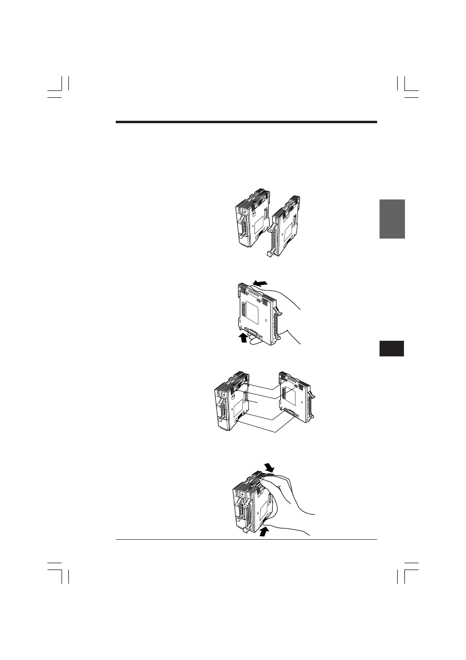
To connect the modules, follow the procedure below.
Connection procedure
To connect two modules as shown below:
1. Open the lock levers.
Open the two lock levers (upper and lower, as shown) of the right module (KV-
C32X) by pivoting them open.
2. Connect the modules.
Insert the lock lever of the right module (KV-C32X) into the slot of the left module
(KV-300 CPU). The bus connector of the KV-300 CPU connects to that of the
KV-C32X.
3. Close the lock levers.
Push down on the lock levers of the right module (KV-C32X) as shown until they
sit flush with the surface of the module. No gap should remain between the
modules.
KV-300
KV-C32X
Bus connector
KVHKA Chap 05.p65
08.3.11, 11:14 AM
179
- LR-TB2000 Series (12 pages)
- LR-TB5000 Series (12 pages)
- LR-ZB250AN/AP (4 pages)
- LR-ZB250AN/P (3 pages)
- LR-ZBxN/P Series (3 pages)
- LR-ZBxxB (3 pages)
- OP-85135 (1 page)
- PZ-G Series (2 pages)
- PZ-V/M (2 pages)
- PS-N10 Series (12 pages)
- PX-10 (10 pages)
- CZ-V21A(P) (10 pages)
- CZ-K1(P) (8 pages)
- CZ-V1 (8 pages)
- FS-N10 Series (6 pages)
- FS-N10 Series (116 pages)
- FS-N15CN (1 page)
- FU-93(Z) (2 pages)
- FU-V Series (2 pages)
- FS-V30 (6 pages)
- FU-A40 (1 page)
- NU/FS-N Series (16 pages)
- FS-V33(P) (8 pages)
- FS-V21 (4 pages)
- FS-V22 (4 pages)
- FS-V11(P) (4 pages)
- FS-V1(P) (4 pages)
- LV-N10 Series (12 pages)
- LV-N10 Series (112 pages)
- LV-S62 (1 page)
- OP-84350 (1 page)
- LV-SA (10 pages)
- LV-SB (12 pages)
- OP-87305 (1 page)
- LV Series (10 pages)
- LV-B102 (1 page)
- EV-108M(U) (1 page)
- EZ Series (1 page)
- EM Series (1 page)
- ES-M1(P) (3 pages)
- EX-V Series (120 pages)
- EX-500(W) Series (16 pages)
- GV Series (10 pages)
- IA Series (8 pages)
- LB-1000(W) (24 pages)