Kv-24ar/dr (relay output type), Visual kv series, Chapter 1 configuration and specifications – KEYENCE Visual KV Series User Manual
Page 49: Terminal layout drawing ■ input circuit diagram, Internal circuit, Sensor
Chapter 1 Configuration and Specifications
1-25
1
1
Visual KV
Series
1.6.2
Terminal Layout Drawings and I/O Circuit Diagrams
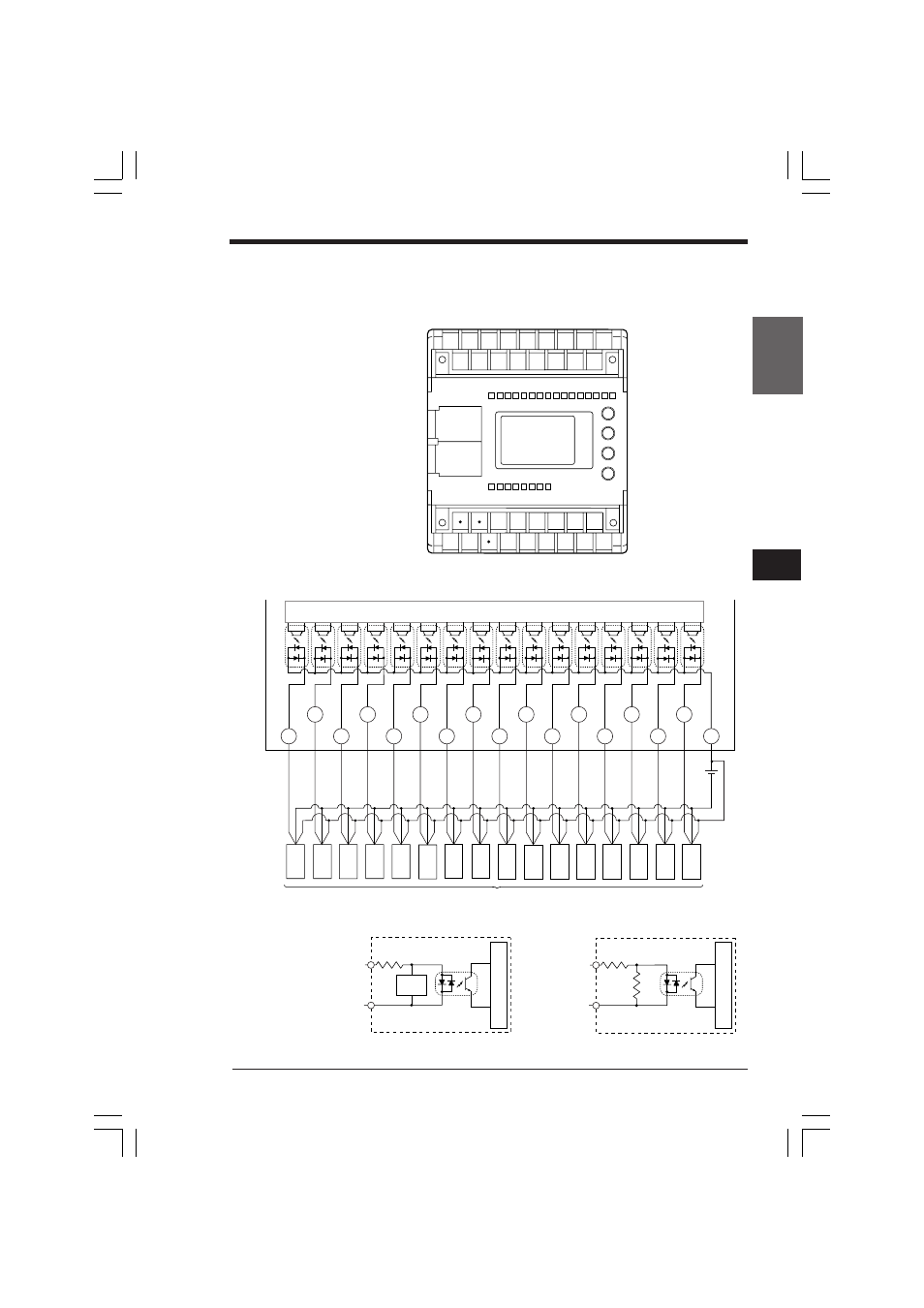
KV-24AR/DR (Relay output type)
■ Terminal layout drawing
■ Input circuit diagram
C1 001 003 005 007 009 011 013 015
000 002 004 006 008 010 012 014
24V 0V
C3 C4
C5 C6 505 507
500 501 502 503 504 506
005
006
007
008
009
011
015
004
002
000
010
012
014
C1
001
003
013
000 to 007
C1
4.3KΩ
008 to 015
C1
4.3KΩ
510Ω
Circuit configuration of inputs 000 to 007
Internal circuit
Three-wire
type
Blue
Black
Brown
Three-wire
type
Blue
Black
Brown
Three-wire
type
Blue
Black
Brown
Three-wire
type
Blue
Black
Brown
Three-wire
type
Blue
Black
Brown
Three-wire
type
Blue
Black
Brown
Three-wire
type
Blue
Black
Brown
Three-wire
type
Blue
Black
Brown
Three-wire
type
Blue
Black
Brown
Three-wire
type
Blue
Black
Brown
Sensor
Three-wire
type
Blue
Black
Brown
Three-wire
type
Blue
Black
Brown
Three-wire
type
Blue
Black
Brown
Three-wire
type
Blue
Black
Brown
Three-wire
type
Blue
Black
Brown
Three-wire
type
Blue
Black
Brown
Photocoupler
insulation
24V/5V
selector
circuit
Internal circuit
Circuit configuration of inputs 008 to 015
Photocoupler
insulation
Internal circuit
1.6 KV-24AR/AT(P)/DR/DT(P) (24-I/O Basic Unit)
KVHKA Chap 01.p65
08.3.11, 11:10 AM
25