KEYENCE FS-V34C(P) User Manual
Instruction manual, Digital fiber sensor 2-output type, Precautions on regulations and standards
1
DIGITAL FIBER SENSOR 2-OUTPUT TYPE
FS-V33(P)/V34(P)/V33C(P)/V34C(P)
Instruction Manual
Read this manual before using the product in order to achieve maximum performance.
Keep this manual in a safe place after reading it so that it can be used at any time.
Precautions on Regulations and Standards
UL Certificate
This product is an UL/C-UL Listed product.
• UL File No.
E301717
• Category
NRKH,NRKH7
• Enclosure
Type 1 (Based on UL50)
Be sure to consider the following specifications when using this product as an UL/
C-UL Listed Product.
• Use the power supply with Class 2 output defined in NFPA70 (NEC: National
Electrical Code).
• Power supply/ Control input/ Control output circuits shall be connected to a sin-
gle Class 2 source only.
• Use with the over current protection device which is rated 24V or more and not
more than 2A.
Option (Sold Separately)
Mounting bracket
End unit
Socket cable
(main unit)
Dedicated for FS-V33C(P)/34C(P)
OP-73880
OP-26751
OP-73864 (cable length: 2 m)
(a set of two)
OP-73865 (cable length: 10 m)
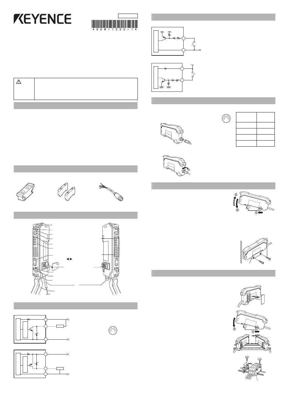
Part Names
Output Circuit Diagram
FS-V33(C)/34(C)
FS-V33 (C)P/V34(C)P
Input Circuit Diagram
FS-V33/34
FS-V33P/34P
Socket Cable (Sold Separately for FS-V33C (P)/V34C (P))
Connecting the Socket Cable
1
Connect the socket to the pin on the
amplifier.
2
Turn the fixing ring on the socket clockwise to fix the socket.
Mounting Unit
Mounting on a DIN Rail
1
Align the claw at the bottom of the main body with the
DIN rail. While pushing the main body in the direction
of the arrow 1, slant it in the direction of the arrow 2.
2
To dismount the sensor, raise the main body in
the direction of the arrow 3 while pushing the
main body in the direction of the arrow 1.
Installation on a Wall (Main Unit Only)
Attach the unit to the optional mounting bracket
(OP-73880), mount them together, and secure
them with two M3 screws as shown in the illus-
tration.
Connecting Multiple Amplifiers
Up to 16 sub units can be connected to one main unit.
1
Remove the protection cover on the side of
the main unit.
2
Install the amplifier one by one on the DIN rail.
3
Engage the two claws of the child unit with the
recesses on the main unit side until you hear a
click sound.
4
Attach the end units (option: OP-26751) to the
both ends of the connected amplifiers in the
same way as in step (2).
5
Sandwich the amplifiers between the end units.
Tighten the screws at the top (two screws x two
units) with a Phillips screwdriver to fix the end units.
Warning
•
This product is just intended to detect the object(s). Do not use this product for
the purpose to protect a human body or a part of human body.
•
This product is not intended for use as explosion-proof product. Do not use this
product in a hazardous location and/or potentially explosive atmosphere.
•
This product is a sensor of DC power supply type. Do not apply AC power. The
product may explode or burn if an AC voltage is applied.
12
1
2
DSC
1
2
DSC
1
2
Operation status indicators (output 1)
Operation status indicators (output 2)
Digital monitor
Setting value
(Displayed in green)
Current value
(Displayed in red)
Dust cover
Fiber lock lever
SET button (SET)
DSC indicator
Manual button
( )
MODE button (MODE)
Channel selection
Expansion protective cover
Expansion connector
Output selector (L/D ON)
*
* FS-V33 (P)/34(P) is a cable, and FS-V33C(P)/34C(P) is a M8 connector.
1
2
3
4
(1) 12-24 VDC
(FS-V33C/V33CP only)
(2) Control output 2
(3) 0 V (FS-V33C/V33CP only)
(4) Control output 1
Pin assignment of the
connector type
Black: control output 1
White: control output 2
0 V
12 to 24 VDC
Brown
*
Black/white
Sensor main cir
cuit
Over
curr
ent pr
otection cir
cuit
Load
Blue
*FS-V33 only
Black: control output 1
White: control output 2
Brown
Blue
*
Black/white
0 V
12 to 24 VDC
Sensor main cir
cuit
Over
curr
ent pr
otection cir
cuit
Load
*FS-V33P only
3.3 VDC
Blue*
Pink (input)
(Short-circuit current
1 mA or less)
PLC, etc.
0 V
Sensor main cir
cuit
* FS-V33 only
Brown*
Pink (input)
(Short-circuit
current 2 mA
or less)
PLC, etc.
12 to 24 VDC
Sensor main cir
cuit
* FS-V33P only
Pin and wire color table
Connected pin
No.
Core wire
cover color
(1)
Brown
(2)
White
(3)
Blue
(4)
Black
3
4
1
2
OP-73880
OP-26751 (a set of two)
96M11292
Document Outline
- Precautions on Regulations and Standards
- Option (Sold Separately)
- Part Names
- Output Circuit Diagram
- Input Circuit Diagram
- Socket Cable (Sold Separately for FS-V33C (P)/V34C (P))
- Mounting Unit
- Connecting Multiple Amplifiers
- Connecting Fiber Unit
- External Input
- Making Sensitivity Settings
- Fine-adjusting Sensitivity
- Percentage Calibration
- Output Selection
- Dynamic Sensitivity Correction (DSC) Function
- Edge Detection Mode
- Area Detection Mode
- Setting the Display Scaling
- Zero-shift Function
- Display Selection
- Key Lock Function
- PIN Number Key Lock Function
- Operation Configuration
- Basic Setting Menu
- Detection Setting Menu
- Display Setting Menu
- System Setting Menu
- Initializing, Saving and Loading the Settings
- Channel Selection Switch 2
- Special Functions of Channel 2
- Specifications
- Error Displays and Corrective Actions
- Hints On Correct Use
- WARRANTY