Kv -300 – KEYENCE Visual KV Series User Manual
Page 201
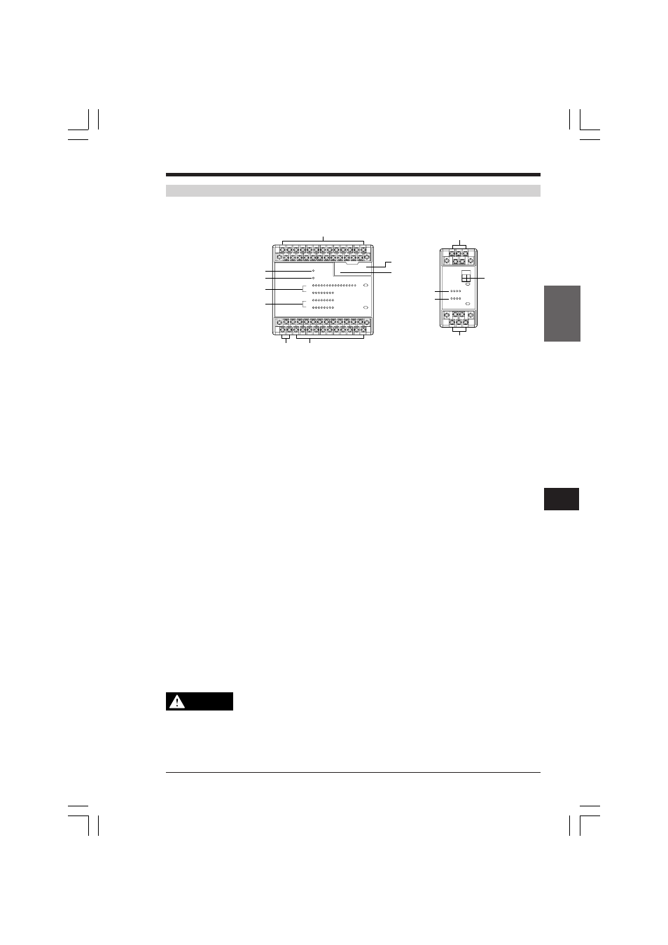
5.2 Module/Unit Specifications
KV
-300
KV-10/80
1
5
Chapter 5 KV-300 Hardware
1-177
For KV-10/80 users
1. Input terminals
Rated input signals for these terminals are 24 VDC.
2. Output terminals
Direct clock pulses as well as ordinary pulses are output through relays 0500 and
0501.
3. Power supply terminals
Supply 24 VDC.
4. POWER indicator
Lights when the power is ON.
5. RUN/ERROR indicator
Lights when the unit is in operation.
Flashes when error occurs during operation.
6. Input indicator
Lights when the input signal is ON.
7. Output indicator
Lights when the output signal is ON.
8. Connector cable port
Connects any KV PLC to the handheld programmer or to the external computer.
To make a connection, open the cover on the PLC.
9. Analog timer (Trimmer)
Open the cover to find the trimmer.
The timer/counter setting and the data on the register can be changed without
using the handheld programmer.
➮ Refer to "2.4.2 Application Instructions" on page 3-95.
To avoid damage to the trimmer, do not use excessive force to turn it and
do not change the setting or data too frequently.
10. Channel setting switches
Assign an I/O channel number to each expansion unit.
KV-40R(W)/40T(2W)
1
4
5
6
7
24 input terminals
3
6
24 input terminals
8
9
1
6
7
10
4 input terminals
4 input terminals
2
KV-8ER(W)/8ET(2W)
CAUTION
KVHKA Chap 05.p65
08.3.11, 11:14 AM
177