3 wiring: kv-300 cpu, Parts and functions, Kv -300 – KEYENCE Visual KV Series User Manual
Page 194
5.2 Module/Unit Specifications
KV
-300
KV-10/80
5
Chapter 5 KV-300 Hardware
1-170
5.2.3
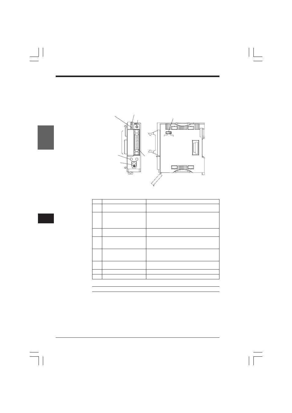
Wiring: KV-300 CPU
Parts and functions
1. SELECT indicator (green)
A
0
1
2
3
4
5
6
7
8
9
10
11
12
13
14
15
B
0
1
2
3
4
5
6
7
8
9
10
11
12
13
14
15
5V
VOLT
24V
INPUT
2. CPU operation indicator
(green, red, flasing
green/red)
3. 32 I/O indicators
(red)
4. Analog timers 0, 1
5. Modular connector
6. SELECT button
7. I/O
connector
(20-pin)
8. Input voltage selection switch
➮ To change the I/O display mode, refer to page 1-191.
No.
Name
Function
1
SELECT indicator (green)
Lights when I/O indicators show CPU I/Os
(0000-0009, 0500-0503).
2
CPU operation indicator LED
Indicates CPU operation status.
(green, red, flashing
Green: RUN mode
green/red)
Red: PROGRAM mode
Alternating green/red flashing: Error indication
3
I/O indicators (red)
Shows I/O status of the module selected with the
SELECT button
4
Analog timer (0, 1)
Turning the trimmer changes the timer/counter set
value and internal register value. Allows easy
adjustment without a Handheld Programmer.
5
Modular connector
RJ-11 Connector for cable (OP-26487 and 26486)
used to connect CPU to Handheld Programmer or
a personal computer.
6
SELECT button
For selecting module whose operation is shown on
I/O indicators
7
I/O connector
Connector (20-pin) for I/O built-in CPU
8
Input voltage selection switch
For selecting input voltage of 24V or 5V
Note: Install the KV-300 CPU immediately to the right of the KV-U4/U5.
KVHKA Chap 05.p65
08.3.11, 11:14 AM
170