4 connecting to external units, Connecting to an external display, Connecting to an ibm pc-at computer – KEYENCE Visual KV Series User Manual
Page 273: Kv -300, When using port 1, When using port 2 (set to rs-232c mode), 3 installation kv-300 series only, Chapter 7 kv-l2 serial interface module, The following figure shows the wiring connections
7.3 Installation
KV-300 Series Only
KV
-300
KV-10/80
Chapter 7 KV-L2 Serial Interface Module
1-249
1
7
7.3.4
Connecting to External Units
Connecting to An External Display
Connect the KV-L2 to the external displays through the RS-232C port. Set the KV-
L2 to Display Interface mode.
Use the serial interface equivalent to the Host Link protocol.
When using port 1
Use optional connection cable OP-90906.
When using port 2 (set to RS-232C mode)
Use optional connection cable OP-20302.
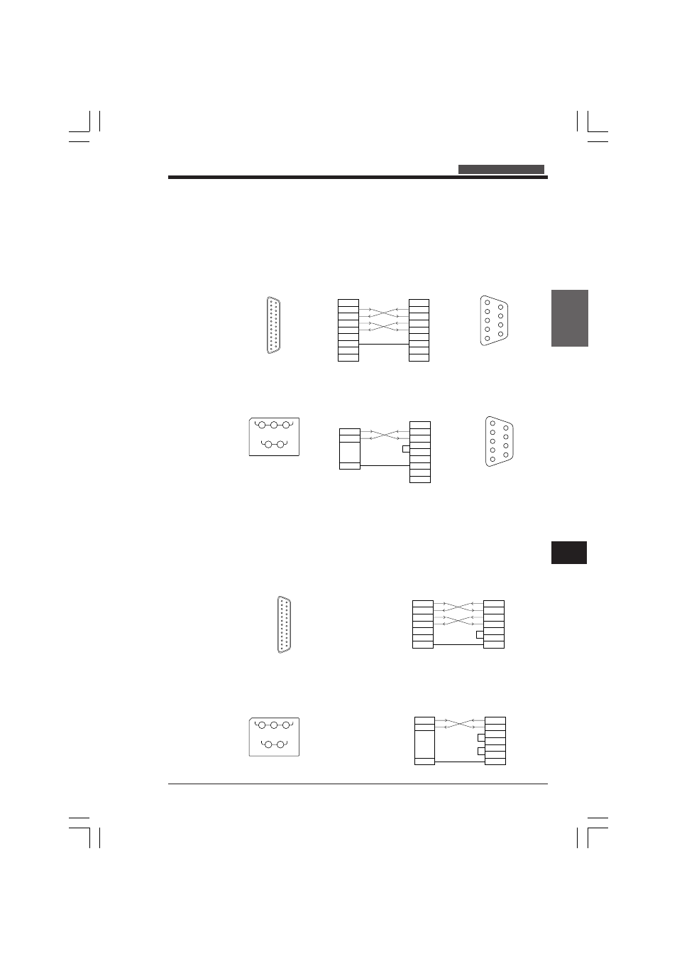
Connecting to an IBM PC-AT Computer
When connecting the KV-L2 to an IBM PC-AT computer, use either RS-232C or RS-
422A mode. To connect through RS-422A mode, the PC must have an RS-422A
interface.
Set the KV-L2 to either KV, Display interface , or non-procedure modes.
When using port 1
An RS-232C cable is required. The following figure shows the wiring connections.
When using port 2 (set to RS-232C mode)
The following figure shows the wiring connections.
SG
(SG)
SDB RDB
SDA
(SD)
RDA
(RD)
1
3
5
2
4
1
2
3
4
5
6
7
SD
RD
SG
SD
RD
RS
CS
DR
SG
Black
Display
8
9
3
5
1
Brown
Blue
54321
9876
D-Sub 9-pin connector
KV-L2 terminal nos.
SG
(SG)
SDB RDB
SDA
(SD)
RDA
(RD)
1
3
5
2
4
KV-L2 terminal nos.
2
3
4
5
6
20
7
SD
RD
SG
SD
RD
RS
CS
DR
ER
SG
KV-L2
PC
3
5
1
D-Sub 25-pin
connector
1
23
45
6
789
1
0
11
12
13
14
15
16
17
18
19
20
21
22
23
24
25
2
3
4
5
7
2
3
4
5
6
20
7
SD
RD
RS
CS
SG
SD
RD
RS
CS
DR
ER
SG
KV-L2
PC
D-Sub 25-pin
connector
1
23
45
6
789
1
0
11
12
13
14
15
16
17
18
19
20
21
22
23
24
25
1
2
3
4
5
6
7
1
2
3
4
5
6
7
SD
RD
RS
CS
SG
SD
RD
RS
CS
SG
8
8
9
9
KV-L2
Display
54321
9876
D-Sub 9-pin connector
KVHKA Chap 07_1to4.p65
08.3.11, 11:18 AM
249