2 configuration, 1 parts and functions, Kv -300 – KEYENCE Visual KV Series User Manual
Page 265
7.2 Configuration
KV
-300
KV-10/80
KV-300 Series Only
Chapter 7 KV-L2 Serial Interface Module
1-241
1
7
7.2
Configuration
7.2.1
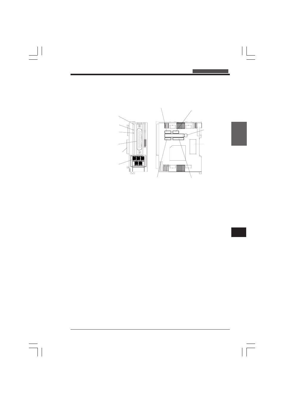
Parts and Functions
1 POWER indicator
2 Port 1 operation
indicator
3 Port 2 operation
indicator
4 Port 1 (RS-232C)
5 Connector to other
modules
6 Port 2
(RS-232C/RS-422A
switchable)
7 Port 2 interface selection switch
8 Terminator selection switch
9
Communications mode setting switch
0 Communications protocol setting switch
A Station no.
setting dial
B Connector to
other modules
1 POWER indicator
Lights when the power supply turns
ON.
2 Port 1 operation indicator
Indicates communication status.
During communication:
Green:
Transmission
Red:
Reception
Yellow:
Transmission and reception
OFF:
Communication disabled
3 Port 2 operation indicator
Indicates communication status.
During communication:
Green:
Transmission
Red:
Reception
Yellow:
Transmission and reception
OFF:
Communication disabled
4 Port 1 (RS-232C)
Port for RS-232C communications.
5 Connector to other modules
For connection to a KV-300 CPU or
external unit.
6 Port 2 (RS-232C/RS-422A)
Switchable between RS-232C and
RS-422A.
7 Port 2 selection switch
For switching between RS-232C
or RS-422 communications
modes.
8 Terminator selection switch
For terminating the modules at the
rightmost and leftmost ends of an
RS-422A connection.
9 Communications mode setting
switch
For setting the operation mode of
the KV-L2.
0 Communications protocol setting
switch
For setting the transmission rate,
data bit, parity, and stop bit.
A Station no. setting dial
For setting the station no. in the
1:n connection sequence.
KVHKA Chap 07_1to4.p65
08.3.11, 11:18 AM
241